Headrest device

Active Publication Date: 2013-11-14
NHK SPRING CO LTD
View PDF39 Cites 7 Cited by
  • Summary
  • Abstract
  • Description
  • Claims
  • Application Information

AI Technical Summary

Benefits of technology

[0015]In the headrest device of the third aspect, the forward projection portion of the headrest projects out toward the front at the upper side or the lower side of the support face of the internal structure. The front end portion of the forward projection portion projects out further toward the front than the support face. The front end portion of the forward projection portion can accordingly be placed in close proximity to and facing a portion of the head of the occupant on the upper side or the lower

Problems solved by technology

The direction and strength of such tilting of the head varies depending on a collision speed of the rear-on collision and differences i

Method used


Image

  • Headrest device
  • Headrest device
  • Headrest device

Examples


first exemplary embodiment

[0025

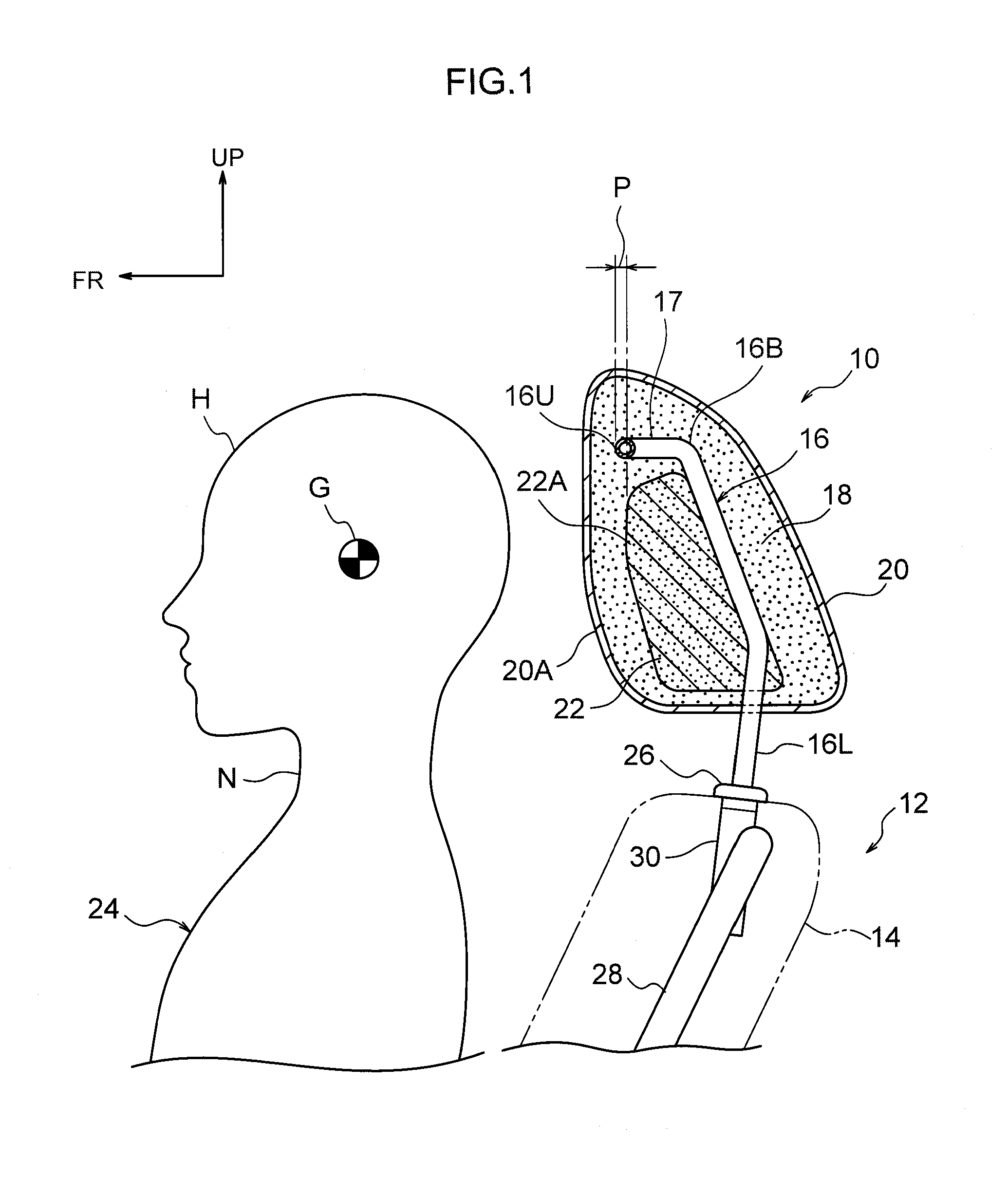
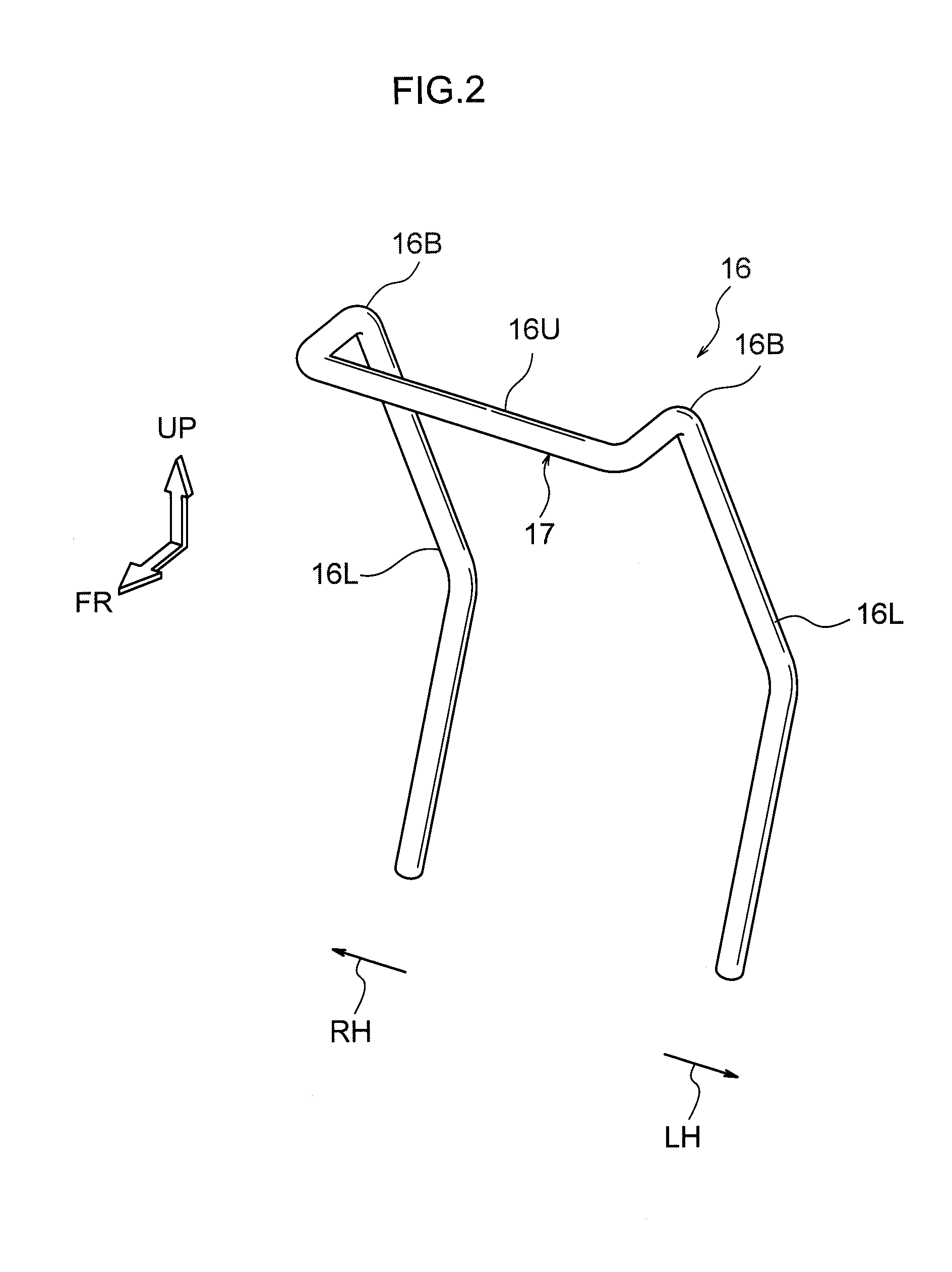
[0026]Explanation follows regarding a headrest device 10 according a first exemplary embodiment of the present invention with reference to FIG. 1 to FIG. 5. Note that in each of the drawings, an arrow FR indicates a vehicle front direction, an arrow UP indicates a vehicle upwards direction, an angle LH indicates a vehicle left hand direction, and an angle RH indicates a vehicle right hand direction as appropriate. Unless specifically indicated, when below explanation refers simply to the front-rear, up-down or left-right directions, these can be considered to be the front and rear in the vehicle front-rear direction, up and down in the vehicle up-down direction, and left and right in the vehicle left-right direction (the vehicle width direction).

[0027]As shown in FIG. 1, the headrest device 10 of the present exemplary embodiment is attached at an upper end portion of a seatback 14 of a vehicle seat 12. The headrest device 10 is configured by a headrest stay 16 serving as a fram...

second exemplary embodiment

[0048

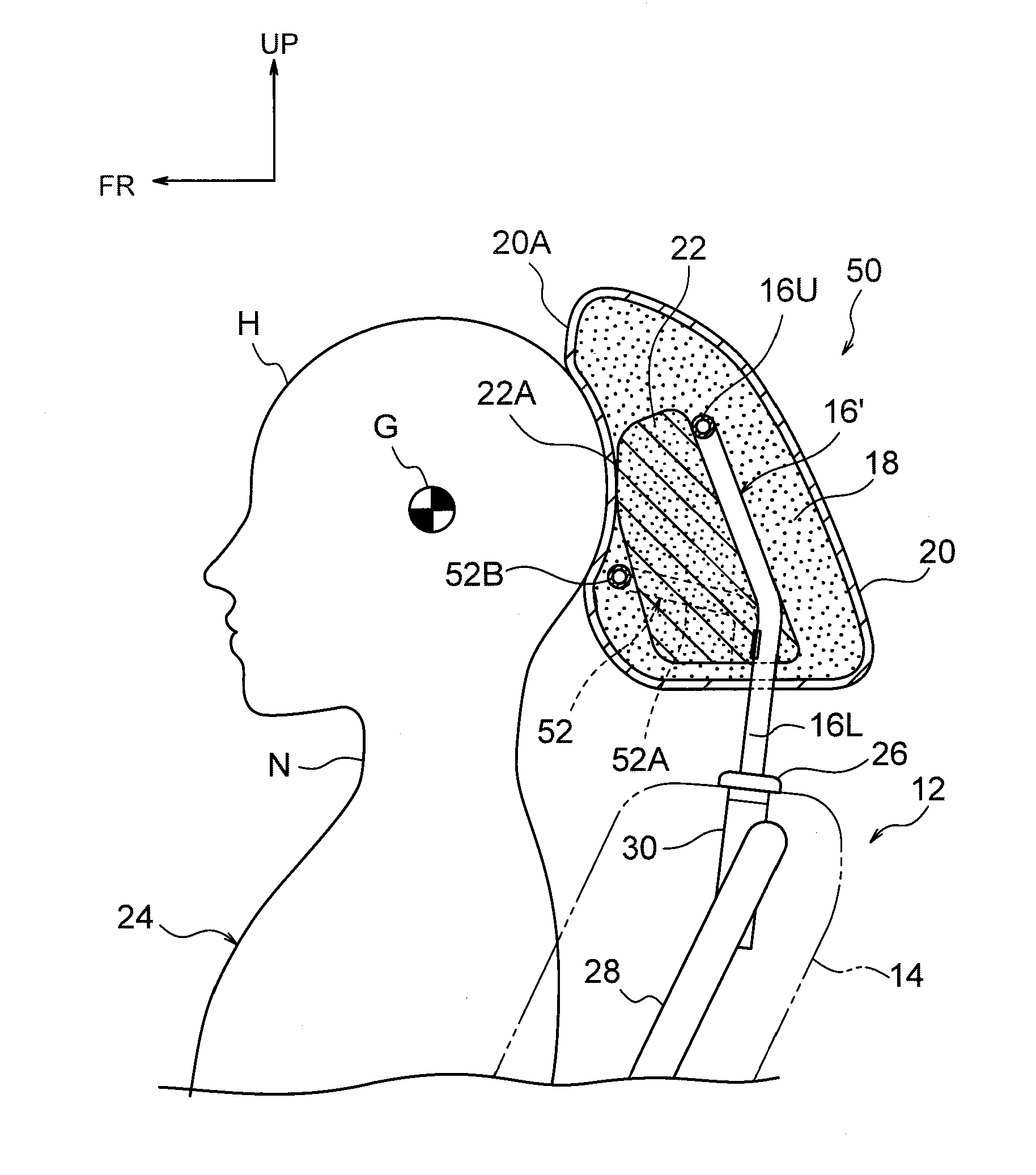
[0049]FIG. 6 is a vertical cross-section as viewed from the vehicle width direction outside, illustrating a configuration of a headrest device 50 and members peripheral thereto according to the second exemplary embodiment of the present invention. The configuration of the present exemplary embodiment is basically the same as in the first exemplary embodiment, however the forward projection portion 17 of the first exemplary embodiment is omitted from a headrest stay 16′ of the present exemplary embodiment. Namely, an upper end portion of the headrest stay 16′ is not bent toward the front, and a connecting portion 16U is positioned to the rear from an upper end portion of an internal structure 22.

[0050]Moreover, in the headrest stay 16′, a forward projection portion 52 that configures a portion of the headrest stay 16′ is fixed at an up-down direction intermediate portion of left and right leg portions 16L. The forward projection portion 52 is formed for example by bend-working m...


PUM


Abstract

A headrest device comprising: a headrest stay that is coupled to an upper end portion of a seatback of a vehicle seat, and that supports a headrest pad; an internal structure that is embedded inside the headrest pad, that is supported from a rear by the headrest stay, and that supports a head of an occupant from the rear during a vehicle rear-on collision via a support face that is formed at a front face of the internal structure; and a forward projection portion that is configured by a portion of the headrest stay that projects forward, that is disposed at an upper side or a lower side of the support face within the headrest pad, and that suppresses the head supported by the support face from tilting backward or tilting forward by pivoting about the support face as a pivoting center.

Description

CROSS-REFERENCE TO RELATED APPLICATION[0001]This application claims priority under 35 USC 119 from Japanese Patent Application No. 2012-97935 filed on Apr. 23, 2012, the disclosure of which is incorporated by reference herein.BACKGROUND OF THE INVENTION[0002]1. Technical Field[0003]The present invention relates to a headrest device.[0004]2. Related Art[0005]In a headrest disclosed in Japanese Patent No. 4431449, a core member configured from for example a hard urethane foam is fixed at an upper end side of a stay. An upper portion of a front face of the core member is formed with a protrusion that protrudes out toward the front, and a lower portion of the front face is formed with a recess. A pad portion is made thickest at a location in front of the recess, and this thick portion of the pad secures comfort of an occupant during normal use.[0006]However, in a rear-on collision, an upper body of the occupant is thrown toward the rear and moves upwards. A head of the occupant is there...

Claims


Application Information

Patent Timeline
IPC IPC(8): B60N2/42B60N2/90
CPCB60N2/4228B60N2/888A47C7/38
Inventor MUNEMURA, NOZOMUNAGAI, KENSUKEHISAMOTO, TADANORI
Owner NHK SPRING CO LTD
Why Eureka
Try Eureka