

Protective device with flange plastic-coated steel tube and protective packaging method thereof
A technology for plastic-coated steel pipes and protection devices, which is applied in the directions of packaging, transportation, packaging, and closing, can solve the problems of reducing the service life of plastic-coated steel pipes, contact wear, scratches and bumps of plastic-coated steel pipes, and achieves improved protection performance, The effect of reducing the contact wear phenomenon of the inner surface wall
- Summary
- Abstract
- Description
- Claims
- Application Information
AI Technical Summary
Problems solved by technology
Method used
Image

Examples
Embodiment 1
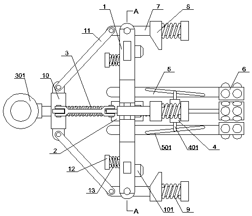
[0036] see Figure 1-6 , the present invention provides a technical solution: a protection device for a plastic-coated steel pipe with a flange, including a mounting plate 1, a stud 3, an inner support frame 5 and an outer buckle frame 7, and the center of the mounting plate 1 is fixedly connected with a screw Set 2, the inner side of the screw sleeve 2 is screwed and connected with a stud 3, the left end of the stud 3 is fixedly connected with a hoisting ring 301, the right end of the stud 3 is rotatably connected with a turntable 4, and the inside of the mounting plate 1 is located outside the screw sleeve 2 Four groups of inner brackets 5 distributed in a circular array are connected by rotation, and the inside of the four groups of inner brackets 5 is provided with a chute 501. The outer circumference is rotatably connected with four sets of outer buckle frames 7 distributed in a circular array, the outside of the stud 3 is located on the right side of the hoisting ring 30...
Embodiment 2
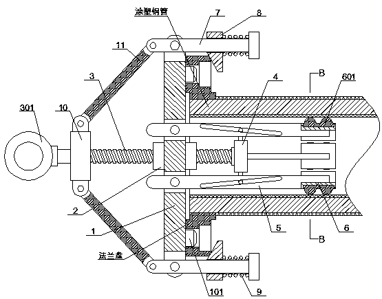
[0038] Specifically, such as figure 1 , figure 2 and Figure 4As shown, the right end surface of the mounting plate 1 is fixedly connected with multiple sets of positioning columns 101 distributed in a circular array, and the outside of the four sets of outer buckle frames 7 are all provided with inclined blocks 8, and the outside of the four sets of outer buckle frames 7 are located on the outside of the outer buckle A squeeze spring 9 is sleeved between the right end of the frame 7 and the right end face of the inclined block 8, and the right ends of the four sets of inner brackets 5 are fixedly connected with an arc bar 6, and the outer end face of the arc bar 6 is embedded with a rubber gasket 601 , and the outside of the rubber gasket 601 is equidistantly fixedly connected with multiple groups of convex balls 602, and the setting of the positioning column 101 facilitates the butt joint processing between the mounting plate 1 and the flange plate, and reduces the gap bet...
Embodiment 3
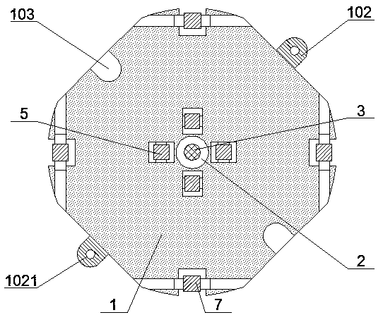
[0040] Specifically, such as figure 1 , image 3 , Figure 5 and Figure 6 As shown, two groups of assembly blocks 102 are symmetrically fixedly connected to the outer periphery of the installation disk 1, and two groups of assembly grooves 103 are symmetrically opened on the outer periphery of the installation disk 1 between the two groups of assembly blocks 102, and the left end surface of the installation disk 1 is close to the two groups of assembly blocks. One side of the groove 103 is slidably embedded with a sliding column 12 that runs through the assembly groove 103, and the outside of the sliding column 12 is sleeved with a tension spring 13, and the two ends of the tension spring 13 are connected to the left end of the sliding column 12 and the mounting plate 1 respectively. The left end face of the two sets of assembly blocks 102 are provided with sliding holes 1021 on the side close to the sliding column 12, and the sliding holes 1021 and the sliding column 12 ar...
PUM
 Abstract
Description
Claims
Application Information