Inner ventilated motor

A technology of electric motor and internal air, which is applied in the direction of electric components, electrical components, electromechanical devices, etc., to achieve the effect of short heat flow path, reduced external size and weight, and high protection performance

Inactive Publication Date: 2010-06-23
昆明电机厂有限责任公司
View PDF0 Cites 0 Cited by
  • Summary
  • Abstract
  • Description
  • Claims
  • Application Information

AI Technical Summary

Problems solved by technology

However, the second structure is not suitable for sites

Method used


Image

  • Inner ventilated motor
  • Inner ventilated motor
  • Inner ventilated motor

Examples


Example Embodiment

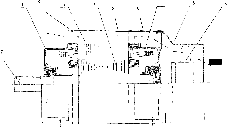
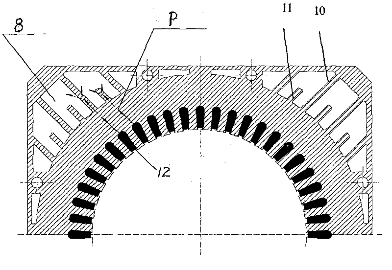
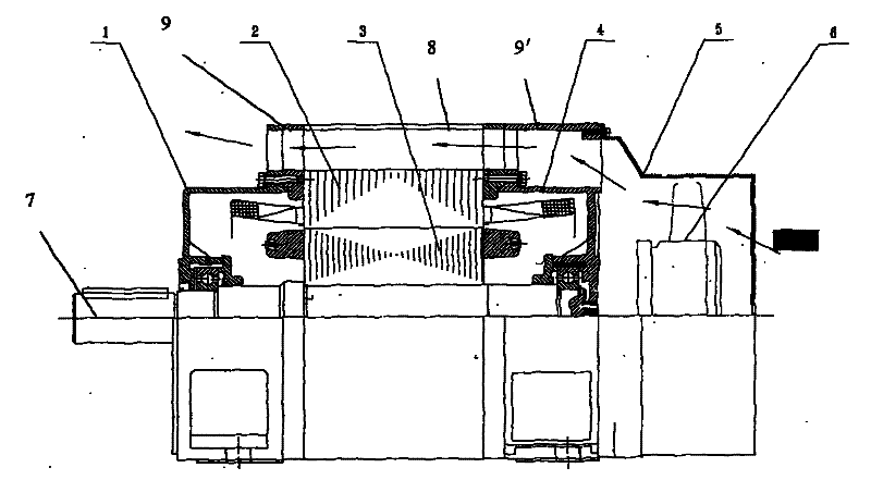
[0011] Such as figure 1 As shown, the present invention includes a motor central shaft 7, a motor rotor 3, a stator 2, and a left end cover 3 and a right end cover 4 packaged on both ends of the rotor and stator. In this embodiment, the fan 6 is arranged at the outer end of the right end cover and is covered by a wind hood 5. The stator core yoke is provided with a through stator air guide hole 8 along the axial direction. Correspondingly, the left end cover 3 and the right end cover 4 are provided with a through end cover air guide hole opposite to the stator air guide hole along the axial direction. 9, 9', end cover air guide holes 9, 9'are annular air guide holes. Such as figure 2 As shown, the stator air guide hole 8 surrounds the stator core and is opened in a yoke of the same width as the stator core. The stator air guide hole 8 is provided with radial partitions 10 penetrating the axial direction. Radial tooth plates 11 are alternately arranged between. The stator ai...


PUM


Abstract

The invention discloses an inner ventilated motor, comprising a central shaft (7), a stator (2), a rotor (3), a left end cap (3) and a right end cap (4), wherein the yoke part of a stator iron core is provided with a penetrating stator ducting hole (8) in the axial direction, and the left end cap (3) and the right end cap (4) are provided with penetrating end cap ducting holes (9, 9') which are in butt joint with the stator ducting hole in the axial direction. The invention combines the advantages of sealed external cooling structure with opening direct cooling structure and has favorable repellency and cooling effect.

Description

technical field [0001] The invention belongs to the technical field of electric motor structure. Background technique [0002] The cooling mode of the existing motor is generally fan self-cooling. There are two commonly used cooling structures. The first is a closed external cooling structure. The heat in the motor winding passes through the iron core, the gap between the iron core and the frame or the insulating layer, the frame, the surface of the frame, etc. and the cold air. Carry out energy conversion and take away heat. The second type is an open direct cooling structure. Some of the heat in the motor winding directly forms convective energy transfer with the air, and some passes through the iron core, and the iron core forms convective energy exchange with the air in the radial direction to take away heat. The second structure has a higher specific power density due to its good heat dissipation effect. In the same frame size, the output power is more than one level ...

Claims


Application Information

Patent Timeline
IPC IPC(8): H02K9/02
Inventor 韦文云
Owner 昆明电机厂有限责任公司
Why Eureka
Try Eureka