Method of controlling a switched mode power supply and controller therefor

a power supply and switch mode technology, applied in the direction of power conversion systems, oscillation generators, manipulation for frequency changes, etc., can solve the problems of more complex control, audio noise, and important electrical interferen

Active Publication Date: 2013-11-14
NXP BV
View PDF0 Cites 17 Cited by
  • Summary
  • Abstract
  • Description
  • Claims
  • Application Information

AI Technical Summary

Benefits of technology

The present invention relates to reducing interference with electronic devices that use high-speed signals. More specifically, it addresses issues related to what is known as“jitter”—the variation in timing when transmitting data through wires or cables. To reduce these variations, the invention limits the frequency of the jitter signal to below 1 kHz and maintains its amplitude between 0.9 and 33. This helps to improve the quality of the received data and reduces any potential audio noises caused by the jitter. Additionally, the invention includes a feature called“jitter compensation” that prevents abrupt fluctuations in voltage levels during transmission. These improvements make it easier to design more reliable systems without experiencing disruptions or delays while transferring data.

Problems solved by technology

The technical problem addressed in this patent text is the need for a method to compensate for frequency jitter in SMPS converters, which can result in audio noise and exceed allowable EMI limits. Existing methods, such as adding a copy of the jitter signal to the primary peak current or using a low bandwidth control loop, suffer from disadvantages such as being absolute compensation and being less suited to variable operating points.

Method used


Image

  • Method of controlling a switched mode power supply and controller therefor
  • Method of controlling a switched mode power supply and controller therefor
  • Method of controlling a switched mode power supply and controller therefor

Examples


Embodiment Construction

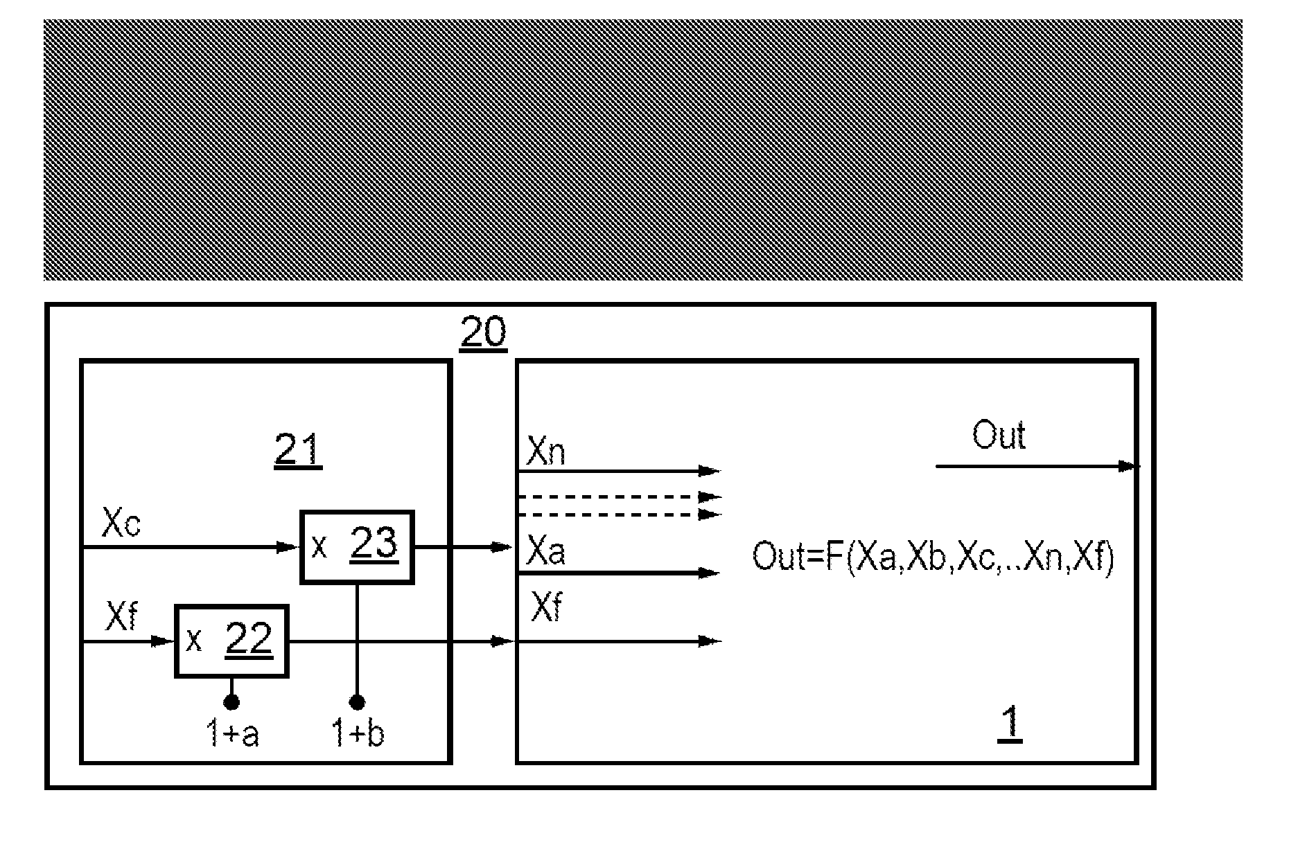
[0048]Embodiments of the invention based in part on the realisation that, for many converter types, such as, without limitation, flyback, boost, buck, and boost-buck, there is at least one other way, besides frequency control, to regulate the output power. Then, in contrast to the known technique of US2005 / 253636 in which a copy of the jitter function is added to the output in order to compensate of the jitter, the inventors have appreciated that a predetermined feed-forward action may be implemented, wherein the effect of the frequency jitter is cancelled by applying an appropriate, correlated, jittering function to one of the other input variables. As a result of the correlated jittering, the system acts, as far as output power is concerned, as if there were no jitter in the first place.

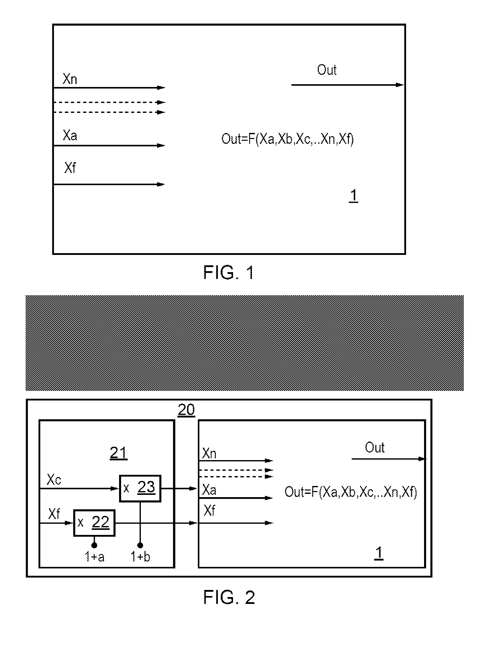
[0049]FIG. 1 shows a SMPS control schema 1 without jitter. The schema has n input variables (Xa, Xb, . . . Xn) including one input variable Xf defining the switching frequency, together with an out...


PUM


Abstract

A controller for an SMPS is disclosed. The controller applies a frequency jitter to the SMPS to reduce Electromagnetic Interference (EMI) and/or audible noise. A second input variable is multiplied by a correlated jitter signal, in order to compensate the output power for the frequency jitter. A corresponding method is also disclosed. Since the jitter compensation occurs within the controller, the method is particularly suitable for controllers operating under different control modes for different output powers (or other output criteria). The multiplicative compensation is applicable across a wide range of converter types.

Description


Claims


Application Information

Patent Timeline
Owner NXP BV
Why Eureka
Try Eureka