Electromagnetic interference immune tissue invasive system

a technology of immune tissue and electromagnetic interference, applied in the field of implantable devices, can solve the problems of affecting the functionality of the pacemaker, the implanted device is vulnerable to severe electromagnetic noise external sources, and so as to and prevent the failure of the tissue implantable devi

Inactive Publication Date: 2002-09-12
MEDTRONIC INC
View PDF99 Cites 134 Cited by
  • Summary
  • Abstract
  • Description
  • Claims
  • Application Information

AI Technical Summary

Benefits of technology

0069] A still further aspect of the present invention is a method for preventing a tissue implantable device failure during magnetic resonance imaging. The method includes determining a quiet period for a tissue implantable device and generating a magnetic resonance imaging pulse during a quiet period of the tissue implantable device.
0070] A further aspect of the present invention is a method for preventing a tissue implantable device failure due to an external electromagnetic field source. The method includes detecting a phase timing of an

Problems solved by technology

The use of the MRI process with patients who have implanted medical assist devices; such as cardiac assist devices or implanted insulin pumps; often presents problems.
Since the sensing systems and conductive elements of these implantable devices are responsive to changes in local electromagnetic fields, the implanted devices are vulnerable to external sources of severe electromagnetic noise, and in particular, to electromagnetic fields emitted during the magnetic resonance imaging (MRI) procedure.
A common implantable pacemaker can, under some circumstances, be susceptible to electrical interference such that the desired functionality of the pacemaker is impaired.
Such electrical interference can damage the circuitry of the cardiac assist systems or cause interference in the proper operation or functionality of the cardiac assist systems.
For example, damage may occur due to high voltages or excessive currents introduced into the cardiac assist system.
Therefore, it is required that such voltages and currents be limited at the input of such cardiac assist systems, e.g., at the interface.
However, such protection, provided by zener diodes and capacitors placed at the input of the medical device, increases the congestion of the medical device circuits, at least one zener diode and one capacitor per input/output connection or interface.
This is contrary to the

Method used


Image

  • Electromagnetic interference immune tissue invasive system
  • Electromagnetic interference immune tissue invasive system
  • Electromagnetic interference immune tissue invasive system

Examples


third embodiment

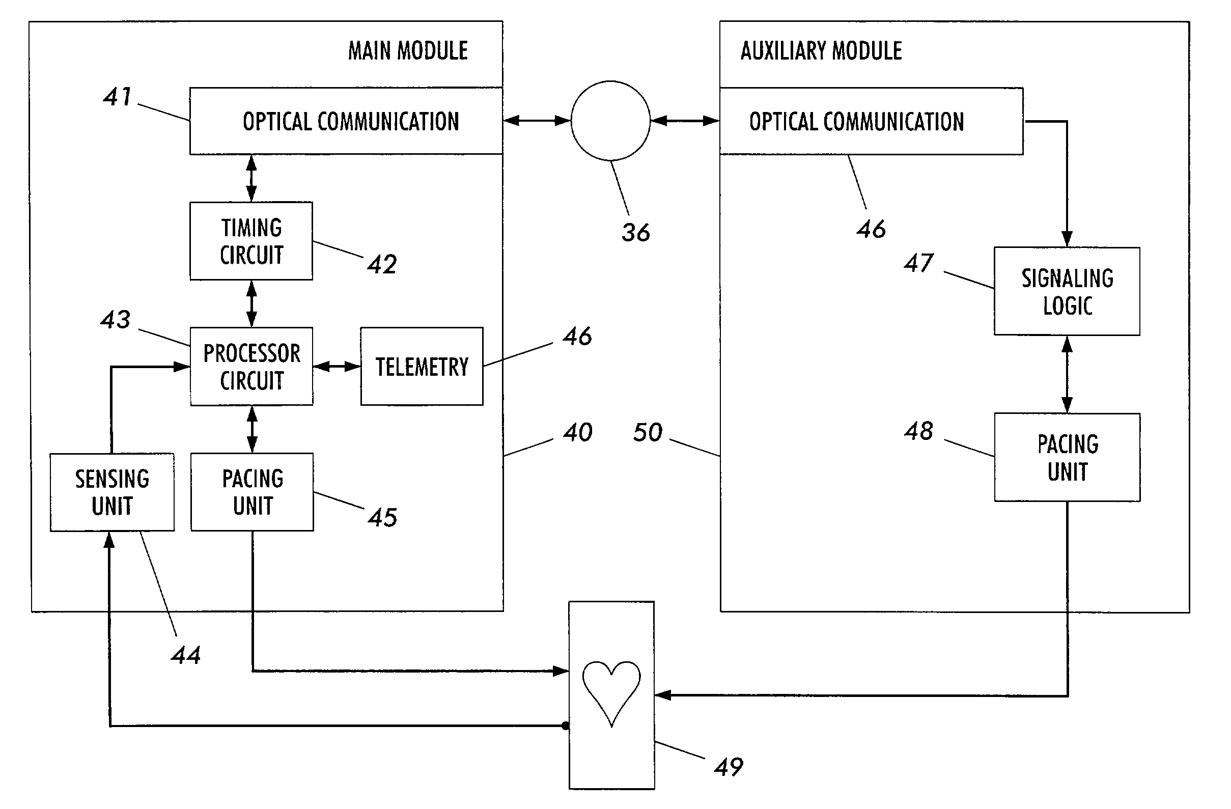
[0355] In the present invention as illustrated in the figures, a cardiac assist system includes a primary device housing. The primary device housing has a control circuit, therein, to perform synchronous cardiac assist operations. The cardiac assist system further includes a secondary device housing that has a control circuit, therein, to perform asynchronous cardiac assist operations

[0356] A detection circuit, located in either the primary or secondary device housing and communicatively coupled to the control circuits, detects an electromagnetic interference insult upon the cardiac assist system. The detection circuit can also be located in a third device housing. Examples of such detection circuits are a thermistor heat detector; a high frequency interference detector; a high voltage detector; and / or an excess current detector.

[0357] The detection circuit is communicatively coupled to the control circuits through a fiber optic communication system and / or through electromagnetic in...

fourth embodiment

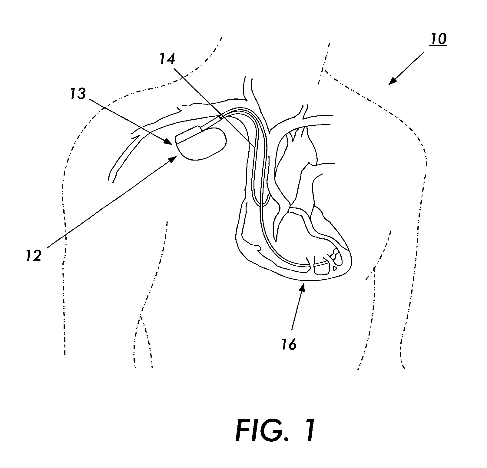
[0365] In the present invention, an implantable pacemaker or a cardiac assist system is used to regulate the heartbeat of a patient. The implantable cardiac assist system is constructed of a primary device housing that has control circuitry therein. This control circuitry may include a control unit such a microprocessor or other logic circuits and digital signal processing circuits. The primary device housing may also include an oscillator, memory, filtering circuitry, an interface, sensors, a power supply, and / or a light source.

[0366] The microprocessor may be an integrated circuit for controlling the operations of the cardiac assist system. The microprocessor integrated circuit can select a mode of operation for the cardiac assist system based on predetermined sensed parameters. In one embodiment, the microprocessor integrated circuit isolates physiological signals using an analog or digital noise filtering circuit.

[0367] The primary device housing also can contain circuitry to de...

fifth embodiment

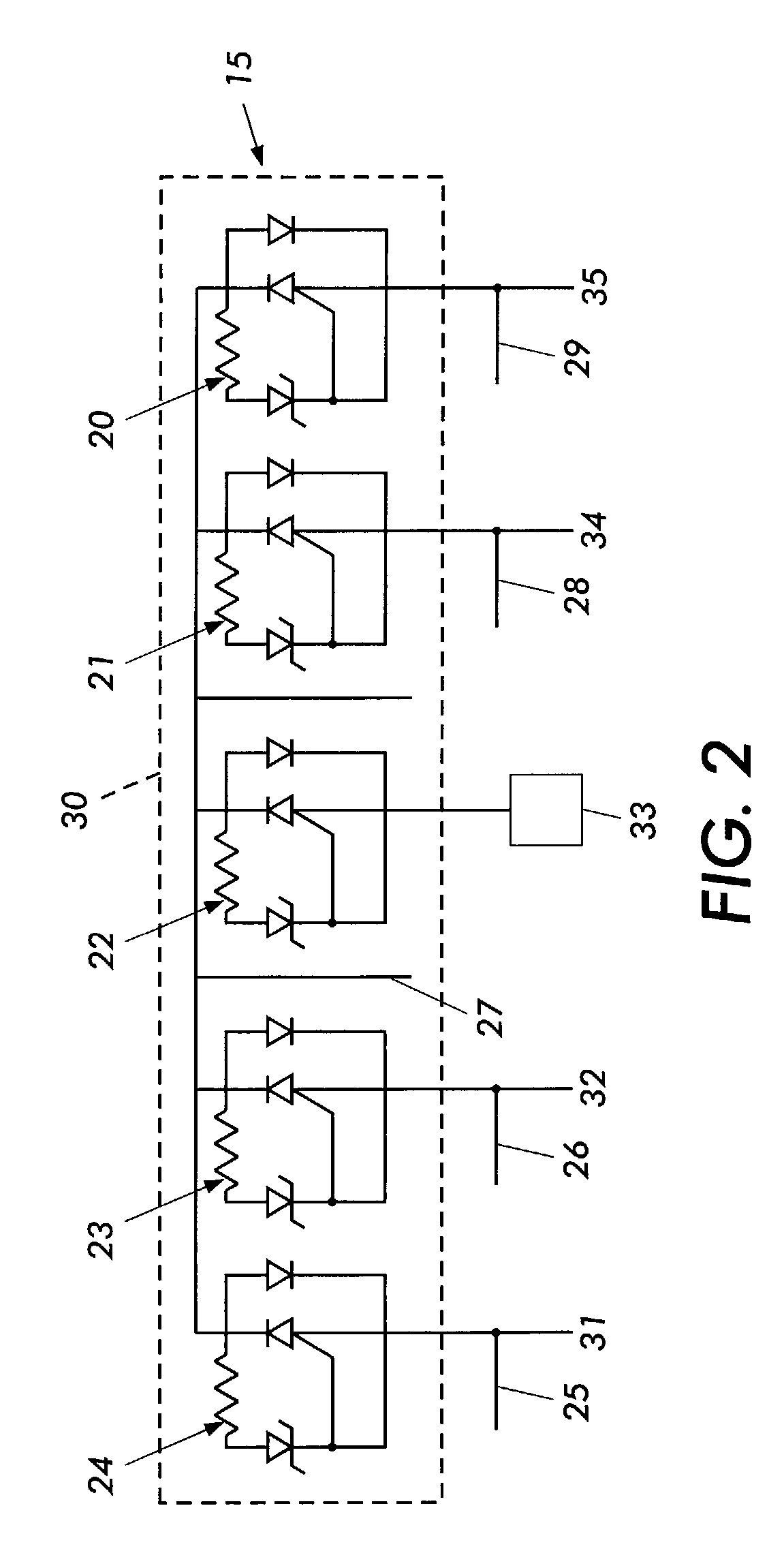
[0375] In the present invention as illustrated in the figures, an implantable cable for transmission of a signal to and from a body tissue of a vertebrate is constructed of a fiber optic bundle having a cylindrical surface of non-immunogenic, physiologically compatible material. The fiber optic bundle is capable of being permanently implanted in a body cavity or subcutaneously. An optical fiber in the fiber optic bundle has a distal end for implantation at or adjacent to the body tissue and a proximal end. The proximal end is adapted to couple to and direct an optical signal source. The distal end is adapted to couple to an optical stimulator. The optical fiber delivers an optical signal intended to cause the optical stimulator located at a distal end to deliver an excitatory stimulus to a selected body tissue. The stimulus causes the selected body tissue to function as desired.

[0376] The optical stimulator is constructed, in a preferred embodiment, is constructed of a photoresponsi...


PUM


Abstract

An electromagnetic immune tissue invasive system includes a primary device housing. The primary device housing having a control circuit therein. A shielding is formed around the primary device housing to shield the primary device housing and any circuits therein from electromagnetic interference. A lead system transmits and receives signals between the primary device housing. The lead system is either a fiber optic system or an electrically shielded electrical lead system.

Description

PRIORITY INFORMATION[0001] This application claims priority from U.S. Provisional Patent Application Serial No. 60 / 269,817, filed on Feb. 20, 2001; the entire contents of which are hereby incorporated by reference.CROSS REFERENCE TO RELATED PATENT APPLICATIONS[0002] The subject matter of co-pending U.S. patent application Ser. No. 09 / 885,867, filed on Jun. 20, 2001, entitled "Controllable, Wearable MRI-Compatible Cardiac Pacemaker With Pulse Carrying Photonic Catheter And VOO Functionality"; co-pending U.S. patent application Ser. No. 09 / 885,868, filed on Jun. 20, 2001, entitled "Controllable, Wearable MRI-Compatible Cardiac Pacemaker With Power Carrying Photonic Catheter And VOO Functionality"; co-pending U.S. patent application Ser. No. 10 / 037,513, filed on Jan. 4, 2002, entitled "Optical Pulse Generator For Battery Powered Photonic Pacemakers And Other Light Driven Medical Stimulation Equipment"; co-pending U.S. patent application Ser. No. 10 / 037,720, filed on Jan. 4, 2002, entit...

Claims


Application Information

Patent Timeline
IPC IPC(8): A61N1/05A61N1/08A61N1/16A61N1/375
CPCA61N1/056A61N1/3718A61N1/375G01R33/285G01R33/288A61N1/086A61N1/37512
Inventor CONNELLY, PATRICK R.MACDONALD, STUART G.
Owner MEDTRONIC INC
Why Eureka
Try Eureka