
Adaptively zippering meshes

a mesh and mesh technology, applied in the field of adaptive mesh zippering, can solve the problems of numerical and computational problems, conventional software applications typically are not able to produce satisfactory results, and conventional software applications introduce significant mesh distortion and irregularities, and achieve the effects of low pre-processing workload, efficient merged, and easy specification

Active Publication Date: 2013-11-14
AUTODESK INC
View PDF2 Cites 21 Cited by
  • Summary
  • Abstract
  • Description
  • Claims
  • Application Information

AI Technical Summary

Benefits of technology

The disclosed technique allows for efficient merging of mesh surface boundaries with minimal distortion and irregularity. The user can easily specify the boundaries, and a zippering algorithm is used to move vertices and refine mesh distortions. This technique reduces the workload for pre-processing and enables merging of meshes with different densities.

Problems solved by technology

Consequently, conventional software applications typically are unable to produce satisfactory results when attempting to merge meshes having different resolutions (e.g., different vertex / triangle densities).
Additionally, even when processing meshes having similar resolutions, conventional software applications introduce significant mesh distortions and irregularities during the merging process.
Such irregularities may produce numerical and computational issues and / or produce visual artifacts during subsequent processing of the mesh.
Moreover, repairing mesh triangles affected by the merging process can be tedious and time-consuming for the end-user.

Method used


Image

  • Adaptively zippering meshes
  • Adaptively zippering meshes
  • Adaptively zippering meshes

Examples


Embodiment Construction

[0024]In the following description, numerous specific details are set forth to provide a more thorough understanding of the present invention. However, it will be apparent to one of skill in the art that the present invention may be practiced without one or more of these specific details. In other instances, well-known features have not been described in order to avoid obscuring the present invention.

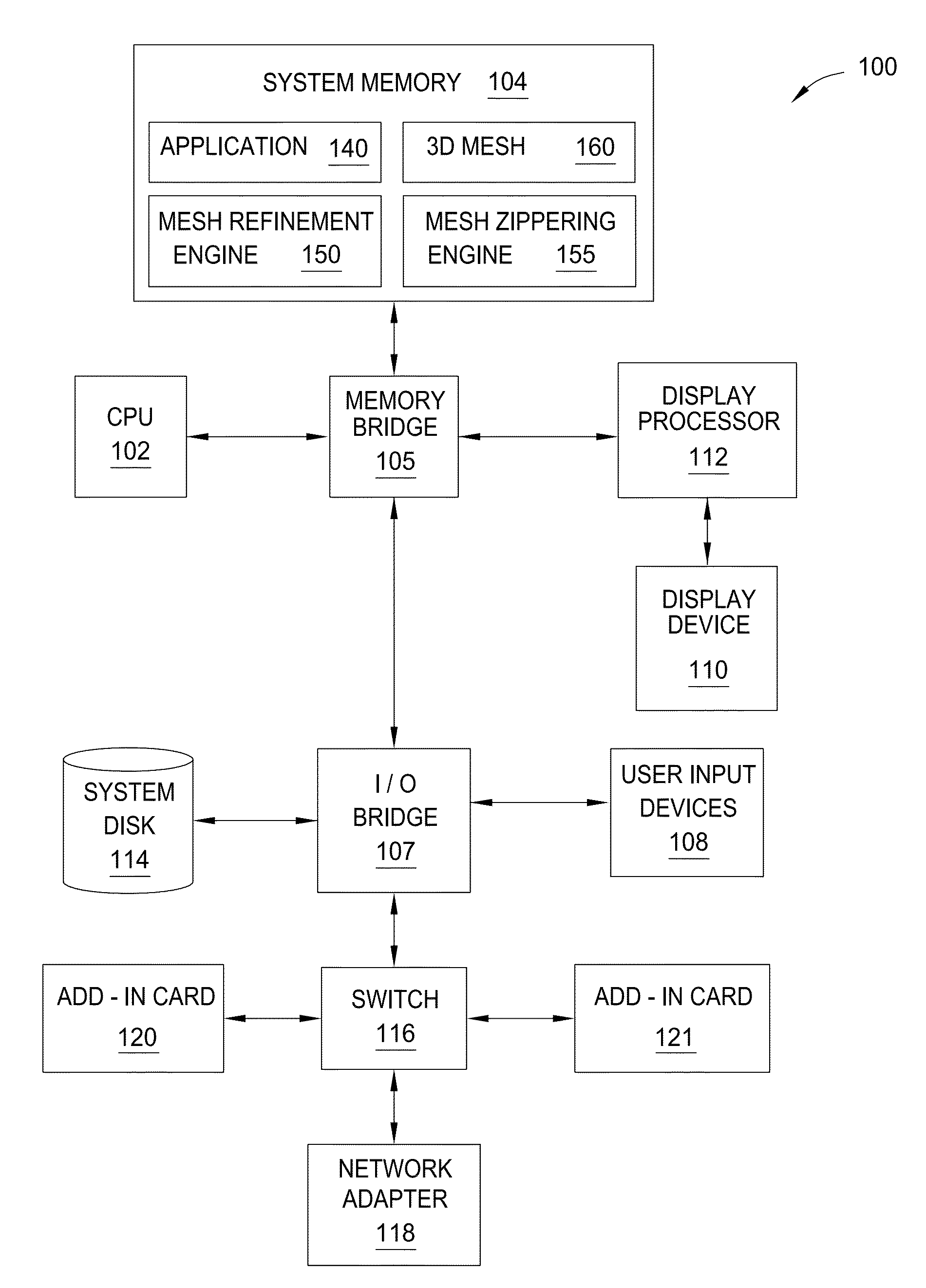
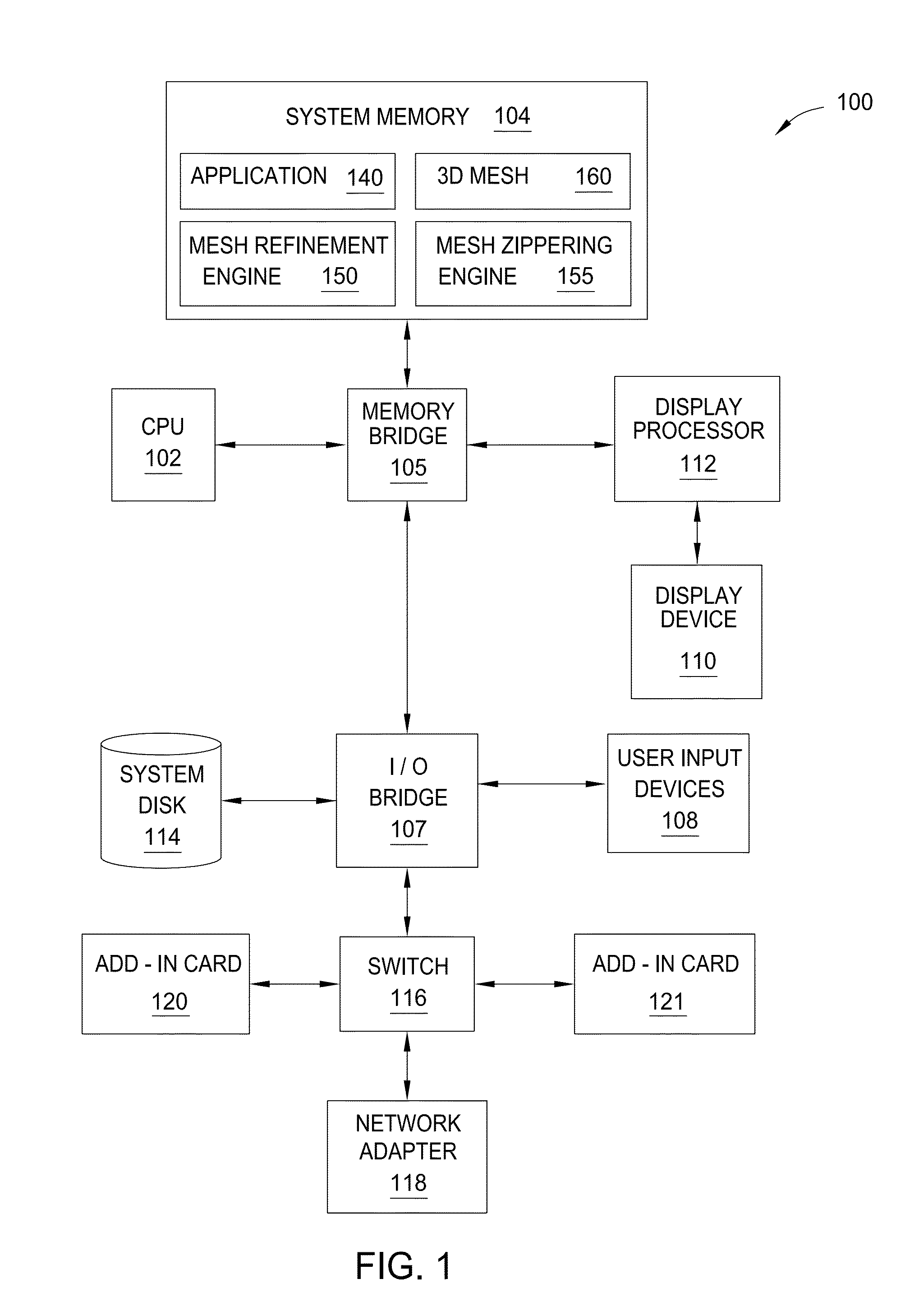
[0025]FIG. 1 illustrates a computing device 100 configured to implement one or more aspects of the present invention. As shown, computing device 100 includes a memory bridge 105 that connects a central processing unit (CPU) 102, an input / output (I / O) bridge 107, a system memory 104, and a display processor 112.

[0026]Computing device 100 may be a computer workstation, a personal computer, video game console, personal digital assistant, mobile phone, mobile device or any other device suitable for practicing one or more embodiments of the present invention. As shown, the central processing...


PUM


Abstract

One embodiment of the present invention sets forth a technique for zippering meshes of primitives. The technique involves identifying a first vertex associated with a first mesh boundary and having a first position and identifying a second vertex that is proximate to the first vertex and associated with a second mesh boundary, where the second vertex has a second position. The technique further involves determining a third position based on the first position, the second position, and a zippering strength factor, where the third position is located in a region between the first position and the second position. Filially, the technique involves moving the first vertex to the third position.

Description

CROSS-REFERENCE TO RELATED APPLICATIONS[0001]This application claims benefit of U.S. Provisional Patent Application Ser. No. 61 / 646,603, filed May 14, 2012, which is herein incorporated by reference in its entirety.BACKGROUND OF THE INVENTION[0002]1. Field of the Invention[0003]Embodiments of the present invention generally relate to computer-aided design (CAD) and, more specifically, to techniques for adaptively zippering meshes.[0004]2. Description of the Related Art[0005]A wide variety of software applications are currently available to end-users, including computer-aided design (CAD) applications, computer graphics applications, and three-dimensional (3D) modeling applications, among others. Many of these software applications allow an end-user to create and modify 2D and / or 3D designs. For example, an end-user may interact with a 3D modeling application to add geometry to a design, remove geometry from a design, extrude portions of the design, or join two or more designs. Such ...

Claims


Application Information

Patent Timeline
IPC IPC(8): G06T19/20
CPCG06T19/20
Inventor SCHMIDT, RYAN MICHAEL
Owner AUTODESK INC
Learn More