Device, system and method for calibration of camera and laser sensor

Active Publication Date: 2013-11-21
AGENCY FOR DEFENSE DEV
View PDF5 Cites 14 Cited by
  • Summary
  • Abstract
  • Description
  • Claims
  • Application Information

AI Technical Summary

Benefits of technology

The present invention provides a calibration device, system, and method for accurately calculating a conversion matrix to determine the position relation between a camera and a laser sensor. This is achieved by using a plane member, an intersection line by the laser sensor, and a plane member image by the camera. The conversion matrix includes both intrinsic and extrinsic parameters of the camera and a coordinate conversion matrix with respect to the camera and the laser sensor. The system allows the position relation between the camera and the laser sensor to be varied, making it easier to detect laser points and pixels. This leads to a more precise calculation of the conversion matrix.

Problems solved by technology

However, these methods may have the following problems.
This may cause a calculation time and a complicated degree to be increased.

Method used


Image

  • Device, system and method for calibration of camera and laser sensor
  • Device, system and method for calibration of camera and laser sensor
  • Device, system and method for calibration of camera and laser sensor

Examples


Embodiment Construction

[0030]Reference will now be made in detail to the preferred embodiments of the present disclosure, examples of which are illustrated in the accompanying drawings.

[0031]Hereinafter, a calibration device by a camera and a laser sensor, a calibration system and a calibration method according to the present disclosure will be explained in more details with reference to the attached drawings. For the sake of brief description with reference to the drawings, the same or equivalent components will be provided with the same reference numbers, and description thereof will not be repeated. A singular expression includes a plural concept unless there is a contextually distinctive difference therebetween.

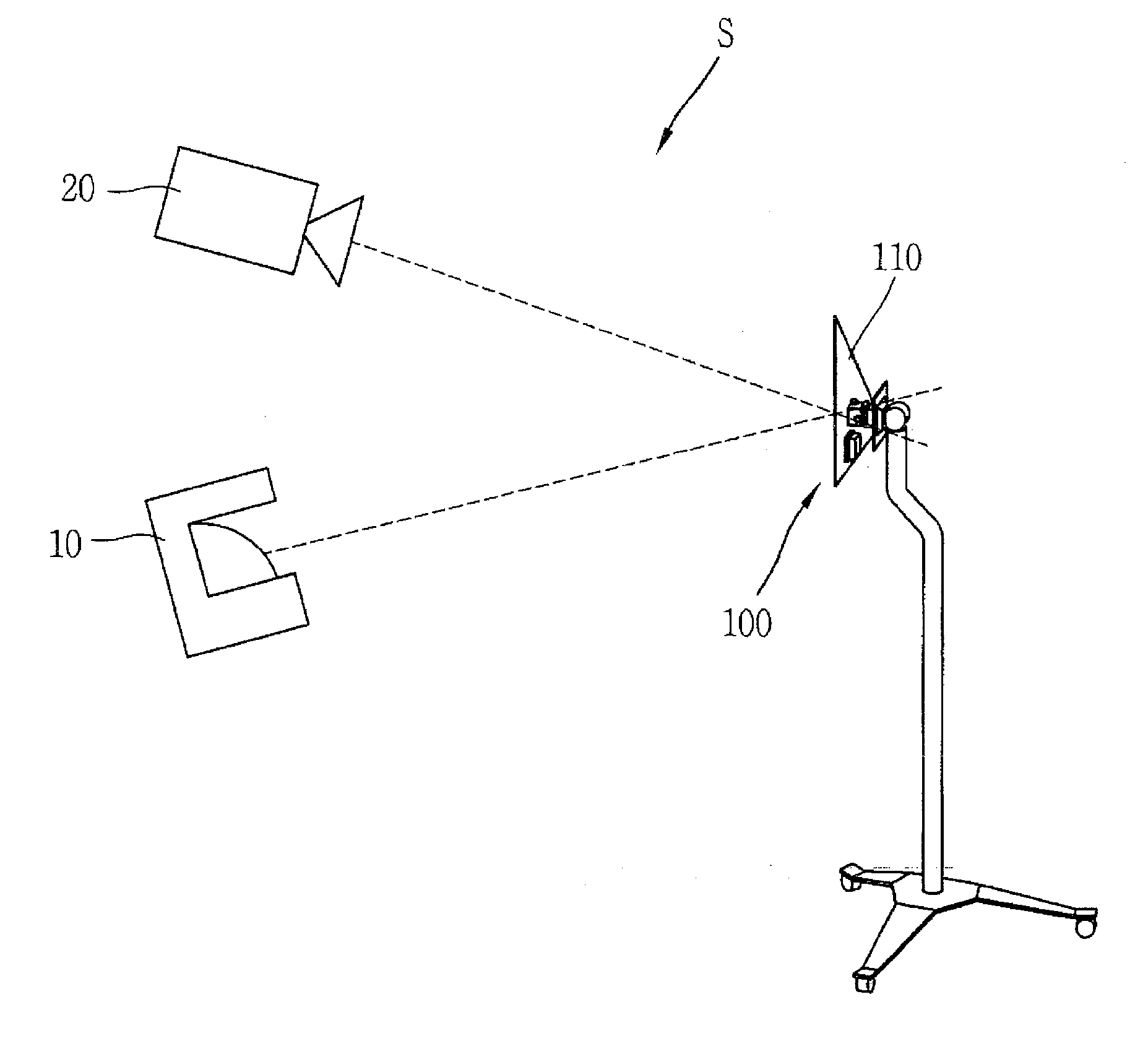
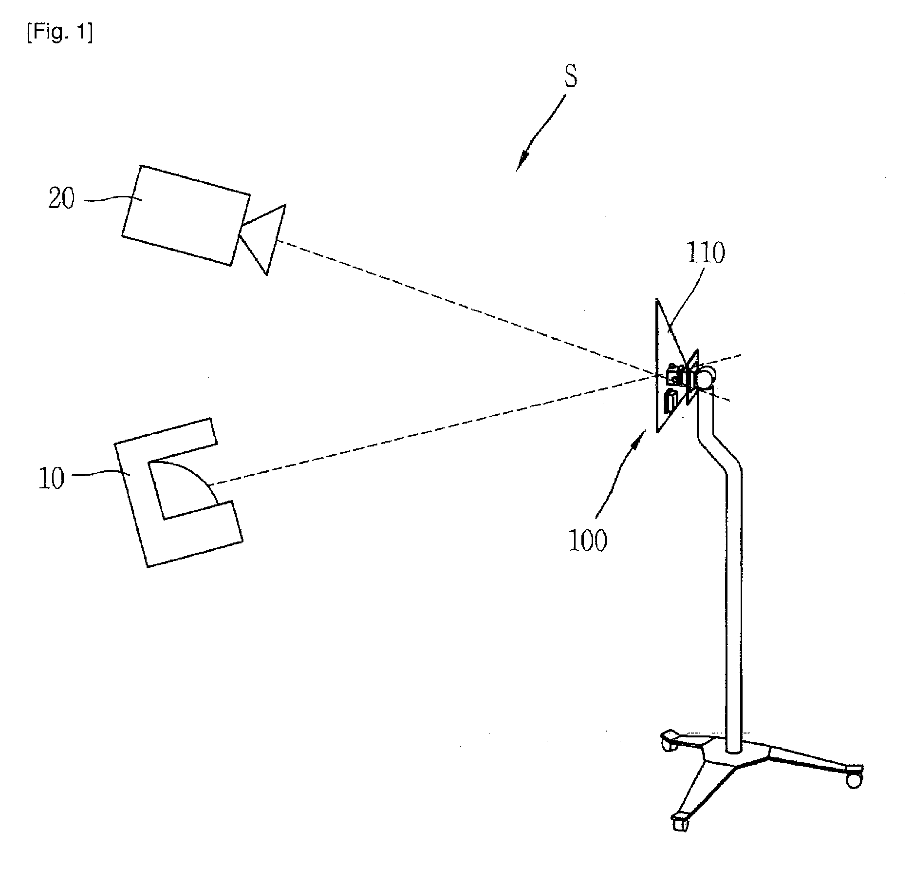
[0032]FIG. 1 is a conceptual view of a calibration system according to the present disclosure.

[0033]A calibration system (S) includes a laser sensor 10 (or laser distance sensor), a camera 20 and a calibration device 100.

[0034]The laser sensor 10 may be implemented as a 2D laser scanner configu...


PUM


Abstract

Disclosed are a calibration device, a calibration system and a calibration method. The calibration device includes a camera configured to capture image information, a laser sensor configured to capture image information, a laser sensor configured to detect distance information, and a calibration module configured to perform a calibration of the camera and the laser sensor by obtaining a relation between the image information and the distance information, wherein the calibration module includes a plane member disposed to intersect a scanning surface of the laser sensor such that an intersection line is generated, and disposed within a capturing range by the camera so as to be captured by the camera, and a controller configured to perform coordinate conversions with respect to the image information and the distance information based on a ratio between one side of the plane member and the intersection line, and based on a plane member image included in the image information. Under these configurations, a calibration is performed through direct coordinate conversions with respect to image information and distance information.

Description

TECHNICAL FIELD[0001]The present disclosure relates to a camera, a system and a method for calibration of a camera, and a laser sensor (laser range finder), and more particularly, to a calibration device for performing coordinate conversions with respect to a camera and a laser sensor, a calibration system, and a calibration method.BACKGROUND ART[0002]Nowadays, a laser sensor (or laser distance sensor) having information on angles and distances is being widely used as fields of robots, autonomous mobile vehicles, etc. are extended. In an industrial field or a military field, a camera image is being much used together with the laser sensor in order to utilize more information. However, in order to use the camera together with the laser sensor, a calibration for obtaining a relation between the laser sensor and the camera has to be performed.[0003]As the conventional calibration method, has been mainly used a method for obtaining a relation between a camera image and a laser distance ...

Claims


Application Information

Patent Timeline
IPC IPC(8): G01C23/00G01S17/87
CPCG01C23/00G01S7/497G01S17/08G01S17/87
Inventor AHN, SEONG YONGCHOE, TOK SONPARK, YONG WOONLEE, WON SEOK
Owner AGENCY FOR DEFENSE DEV
Why Eureka
Try Eureka