Estimation apparatus and method for cylinder intake air amount of internal combustion engine

Active Publication Date: 2015-10-22
MITSUBISHI ELECTRIC CORP
View PDF2 Cites 3 Cited by
  • Summary
  • Abstract
  • Description
  • Claims
  • Application Information

AI Technical Summary

Benefits of technology

The present invention provides an estimation apparatus and method for accurately calculating the amount of air entering a cylinder of an internal combustion engine, particularly in the case of a supercharged engine. This is achieved through the use of a physical model of the intake system that takes into account the response delay from an air flow sensor to the cylinder. Ultimately, this allows for more precise control of engine performance.

Problems solved by technology

On the other hand, this method has such a problem that an estimation error in the cylinder intake air amount during operations including a steady state operation is relatively large due to an error caused by a machine difference from an engine used for the adaptation and an error caused by a difference in environment from that during the adaptation.
Moreover, the cylinder intake air amount during the steady state operation is approximately the same as the AFS intake air amount, and it is considered that a calculation error of the cylinder intake air amount during the steady state operation is relatively small.
However, the related art has the following problem.
The model does not consider a throttle upstream portion extending from the AFS part to the compressor, and thus there is a problem in that a large error is generated in a response characteristic during the transient operation.

Method used


Image

  • Estimation apparatus and method for cylinder intake air amount of internal combustion engine
  • Estimation apparatus and method for cylinder intake air amount of internal combustion engine
  • Estimation apparatus and method for cylinder intake air amount of internal combustion engine

Examples


first embodiment

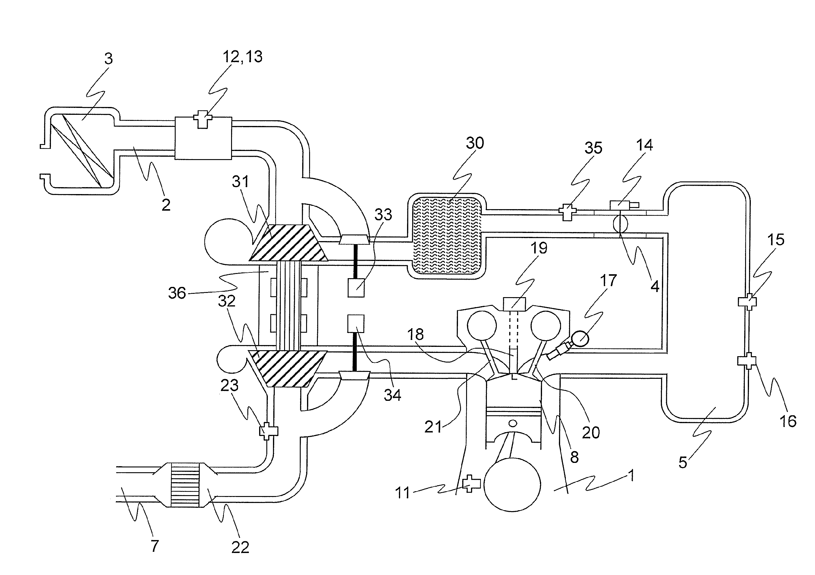
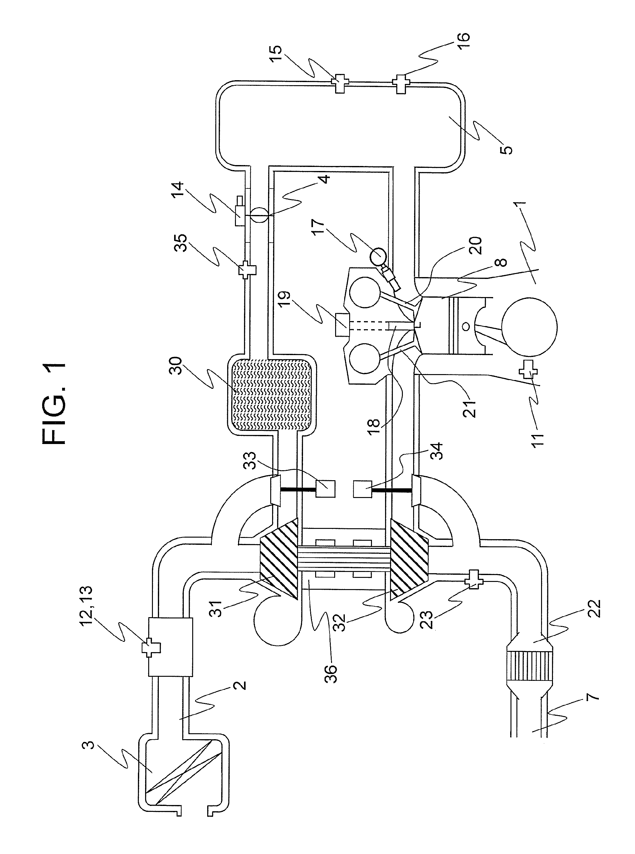
[0027]FIG. 1 is a configuration diagram illustrating a control system for an engine including a turbocharger to which a cylinder intake air amount estimation apparatus for an internal combustion engine according to a first embodiment of the present invention is applied. In FIG. 1, a crank angle sensor 11 for generating an electric signal corresponding to a rotational angle of a crankshaft of an engine 1 is provided for the crankshaft. Moreover, an intake pipe 2 for forming an intake passage and an exhaust pipe 7 for forming an exhaust passage are each connected to a cylinder 8 of the engine 1.

[0028]An air cleaner 3 for cleaning taken outside air is installed on the most upstream portion of the intake pipe 2. An intake air amount detection part (AFS) 12 for generating an electric signal corresponding to an intake air amount and an intake air temperature sensor 13 for generating an electric signal corresponding to an intake air temperature in the intake passage are integrally or indiv...

second embodiment

[0109]In the first embodiment, the control system for an engine including a turbocharger is mentioned as an example, and a description has been given of the physical model of the intake system and the method of installing the physical model in the ECU. Moreover, the physical model can be applied to the control system for an engine including a mechanical supercharger or electric charger as long as the system has the configuration (in the sequence of the compressor 31, the I / C 30, and the throttle valve 4 from the upstream) of the intake system illustrated in FIG. 3 as described above.

[0110]On this occasion, the configuration of the intake system may be different from that in FIG. 3 in the control system for an engine including a mechanical supercharger. In other words, the intake system configured in a sequence of the throttle valve, the mechanical supercharger (hereinafter referred to as “S / C”), and the I / C from the upstream is also general. Then, in a second embodiment of the prese...

third embodiment

[0144]The control system for an engine including a turbocharger is mentioned as an example in the first embodiment, and the control system for an engine including a mechanical supercharger is mentioned as an example in the second embodiment. Thus, a description has been given of the physical model of the intake system and the method of installing the physical model in the ECU.

[0145]However, the calculation method for the cylinder intake air amount based on the physical model of the intake system according to the present invention can be applied to a control system for an engine without a supercharger. The applicability to the T / C system, the S / C system, and the N / A system has an advantage in terms of the common use of the control programs in the ECU. Thus, in a third embodiment according to the present invention, a description is given of a method of applying the calculation method for the cylinder intake air amount based on the physical model of the intake system described before t...


PUM


Abstract

Provided is a cylinder intake air amount estimation apparatus for an internal combustion engine, which is capable of highly precisely calculating a cylinder intake air amount based on an AFS intake air amount in a control system for an engine including a supercharger. A cylinder intake air amount calculation part calculates the cylinder intake air amount based on an intake opening intake air amount by using a physical model of an intake system derived based on a volume efficiency acquired by considering an intake manifold as a reference, which is a volume efficiency of air entering a cylinder from the intake manifold, a virtual intake manifold volume, and a stroke volume per cylinder, the physical model being adapted to the control system for an engine including a supercharger.

Description

BACKGROUND OF THE INVENTION[0001]1. Field of the Invention[0002]The present invention relates to an estimation apparatus and method for a cylinder intake air amount of an internal combustion engine including a supercharger.[0003]2. Description of the Related Art[0004]A control system for an engine including a supercharger has been known in the related art in order to increase an output of an internal combustion engine (hereinafter also referred to as “engine”). As an example of the supercharger, there is known a turbocharger (hereinafter also referred to as “T / C”) in which a compressor driven by rotating a turbine at a high speed by an energy provided by an exhaust gas is installed in an intake system of the engine.[0005]Moreover, as another example of the supercharger, there is known a mechanical supercharger (hereinafter also referred to as “S / C”) in which a compressor driven by a crankshaft via a belt or the like is installed in the intake system of the engine. Moreover, in recen...

Claims


Application Information

Patent Timeline
IPC IPC(8): G01M15/04G01F3/00
CPCG01F3/00G01M15/042F02D41/18F02D41/0007G01F1/72F02D2200/0402F02D2200/0406F02D2200/0411F02D2200/0414Y02T10/12
Inventor HAGARI, HIDEKI
Owner MITSUBISHI ELECTRIC CORP
Why Eureka
Try Eureka