Waveguide and in-vehicle communication system

a technology of in-vehicle communication and waveguide, which is applied in the field of waveguide, can solve the problem of not including specific information about electric power transmission in the proposed waveguid

Active Publication Date: 2013-11-21
YAZAKI CORP
View PDF6 Cites 175 Cited by
  • Summary
  • Abstract
  • Description
  • Claims
  • Application Information

AI Technical Summary

Benefits of technology

[0012]Two or more electric wires may be provided along the outer surface of the waveguide body. With such a configuration, one of the electric wires can serve as the power line and the other one of the electric wires can serve as a ground line to transmit the electric power.
[0013]One or more electric wires may be provided along the outer surface of the waveguide body. With such a configuration, one of the electric wires can serve as the power line and one of the conductive coating layers can serve as a ground line to transmit the electric power.

Problems solved by technology

However, there is no specific information about electric power transmission in the proposed waveguides.

Method used


Image

  • Waveguide and in-vehicle communication system
  • Waveguide and in-vehicle communication system
  • Waveguide and in-vehicle communication system

Examples


first embodiment

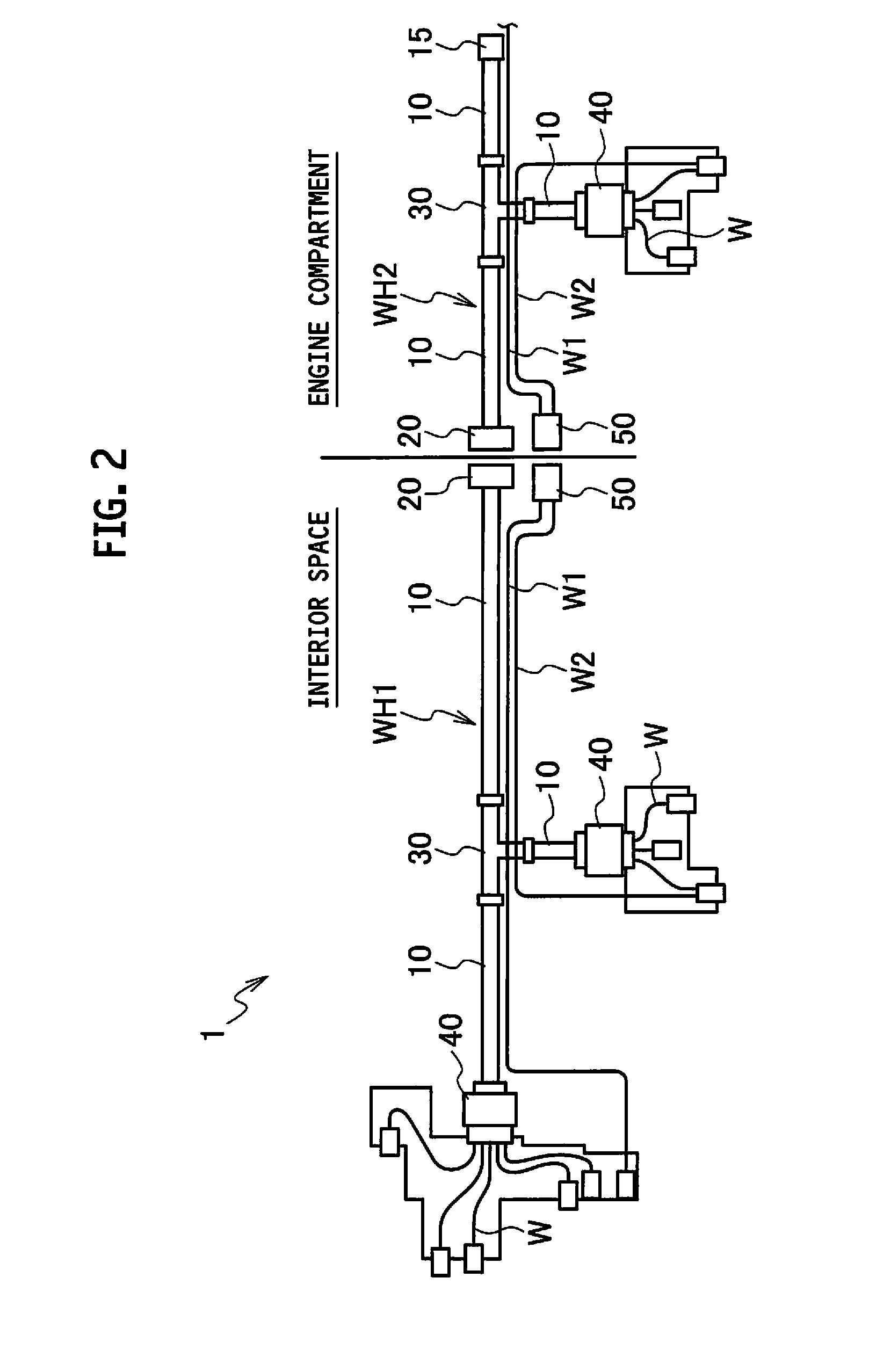
[0031]FIGS. 2 to 4 illustrate a first embodiment of the present invention.

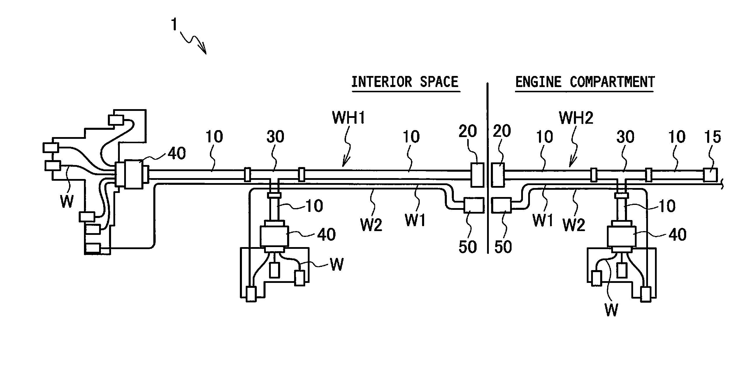
[0032]As illustrated in FIG. 2, an in-vehicle communication system 1 according to the first embodiment is installed across the boundary between an interior space and an engine compartment, and includes a first waveguide wire harness WH1 installed in the interior space and a second waveguide wire harness WH2 installed in the engine compartment. Each of the first waveguide wire harness WH1 and the second waveguide wire harness WH2 includes waveguides 10, a waveguide flange 20, a branch 30 provided at a branched portion of the waveguides 10, and an intelligent connector 40 attached to one of the end portions of the waveguides 10.

[0033]The waveguides 10 of the first waveguide wire harness WH1 and the waveguides 10 of the second waveguide wire harness WH2 are mutually connected via each waveguide flange 20 at the boundary between the interior space and the engine compartment.

[0034]Each of the first waveguide wire h...

second embodiment

[0061]FIG. 9 illustrates a second embodiment of the present invention.

[0062]As illustrated in FIG. 9, a waveguide wire harness WH used in an in-vehicle communication system includes waveguides 10, and electronic components such as electronic control units (ECUs) 60 and intelligent connectors 40 attached to terminals of the waveguides 10. The waveguides 10 are branched by use of branches (not illustrated).

[0063]The configuration of the waveguides 10 according to the second embodiment are the same as that of the first embodiment, and the explanation thereof is thus omitted. In addition, FIG. 9 does not illustrate the two electric wires. The waveguides 10 may be used any of the waveguides 10A to 10D according to the respective modified examples of the first embodiment. Each of the ECUs 60 is a controller that includes similar functions of the intelligent connector 40 in the first embodiment.

[0064]Since the waveguide body according to the second embodiment is also flexibly formed, cabli...


PUM


Abstract

A waveguide includes a waveguide body which is hollow inside and made from a shape-retentive material, and a conductive inner coating layer which is electrically conductive and provided on an inner surface of the waveguide body. The waveguide uses an inner space of the conductive inner coating layer as a transmission path to transmit electromagnetic waves as signals. Two electric wires provided along the outer surface of the waveguide body serve respectively as a power line and a ground line to transmit electric power.

Description

BACKGROUND OF THE INVENTION[0001]1. Field of the Invention[0002]The present invention relates to a waveguide for transmitting electromagnetic waves, and an in-vehicle communication system using the waveguide.[0003]2. Description of the Related Art[0004]An in-vehicle communication system employing a wire harness using electric wires is well-known. FIG. 1 illustrates such a conventional in-vehicle communication system. A conventional in-vehicle communication system 100 in FIG. 1 includes a first wire harness 101 installed in an interior space, and a second wire harness 102 installed in an engine compartment. The first wire harness 101 includes a plurality of electric wires W, and a plurality of connectors 111 connected to both sides of each electric wire W. The second wire harness 102 includes a plurality of electric wires W, and a plurality of connectors 112 connected to both sides of each electric wire W. The electric wires W are tied together into a small diameter with, for example...

Claims


Application Information

Patent Timeline
Patent Type & Authority Applications(United States)
IPC IPC(8): H01P3/12
CPCH01P3/12H01P3/127
Inventor MITA, AKIRAOKADA, MASAAKIMATSUMOTO, TAKUOGOHARA, TAKASHI
Owner YAZAKI CORP
Why Eureka
Try Eureka