Sintering chamber structure

a sintering chamber and structure technology, applied in the direction of charging supports, lighting and heating apparatus, furniture, etc., can solve the problems of wasting hard for a traditional sintering cavity to be sintered, and most metal parts, so as to achieve the effect of effective adjustment of the internal space of the sintering cavity and productive volume of sintering

Inactive Publication Date: 2013-11-21
CHENG UEI PRECISION IND CO LTD
View PDF8 Cites 7 Cited by
  • Summary
  • Abstract
  • Description
  • Claims
  • Application Information

AI Technical Summary

Benefits of technology

[0008]Accordingly, an object of the present invention is to provide a sintering chamber structure having a detachable structure intended to provide appropriate room for storing different sizes of articles so as to effectively adjust an internal space of a sintering chamber, and achieve the productive volume of sintering.

Problems solved by technology

However, most metal parts are not preferable for being machined, and they can be only processed with the heat-treatment, polishing, or electroplating.
Because the two side walls of the traditional sintering cavity are fixedly disposed, the sintering cavity is not allowed to change the intervals between the slabs for storing articles of different sizes at a time.
In other words, the intervals between the slabs may too small to be applied to large articles, while too large intervals for small articles seems to be wasted on the space, and both instances cause waste of internal space of the sintering cavity.
Thus it is hard for a traditional sintering cavity to be sintered in the productive volume and improve yield rate.
Although a sintering cavity can be specifically designed to form various intervals of the slabs matching different sizes of articles, it takes considerable time and cost for a productive department to change production lines regularly.

Method used


Image

  • Sintering chamber structure
  • Sintering chamber structure
  • Sintering chamber structure

Examples


first embodiment

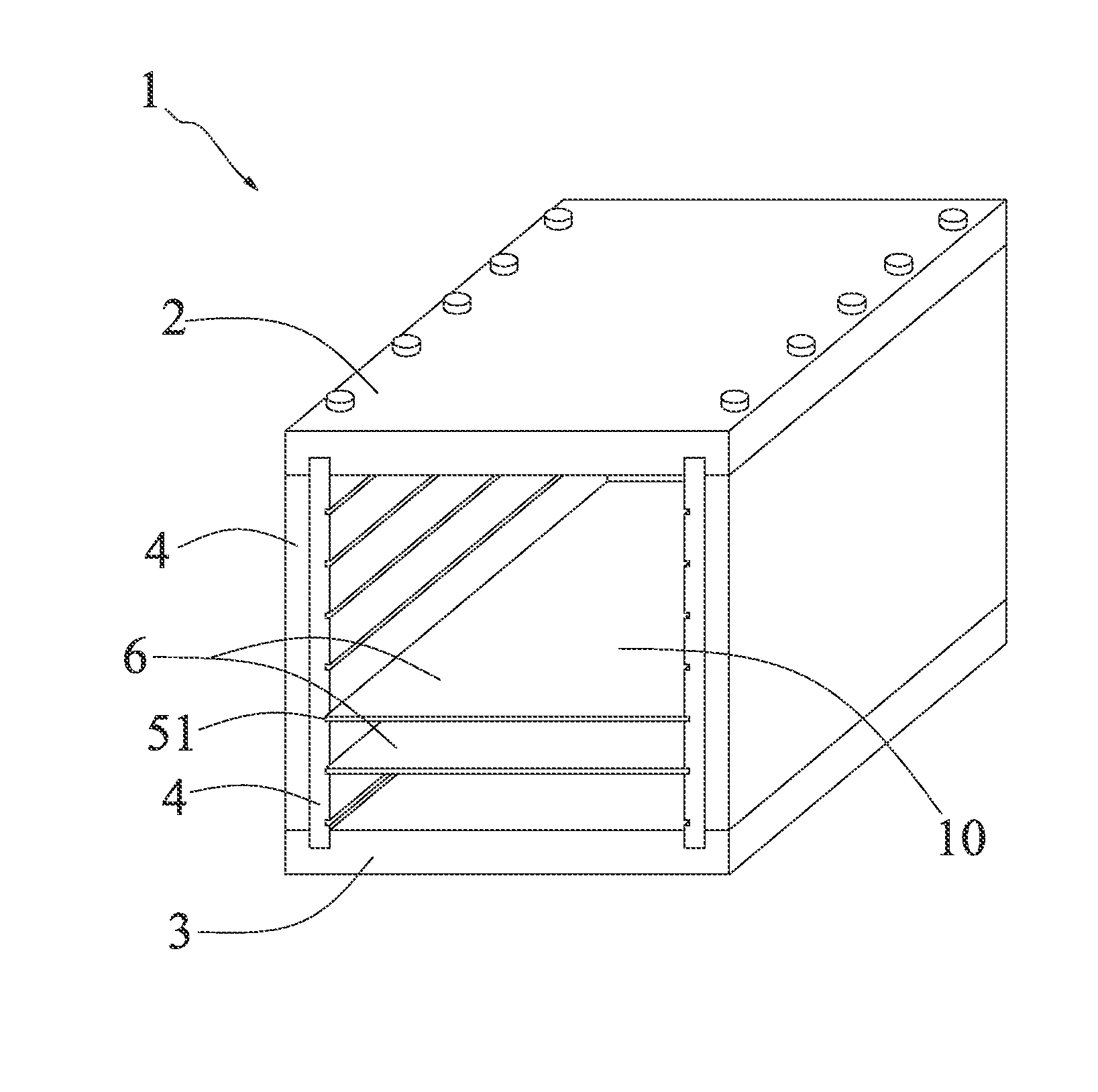
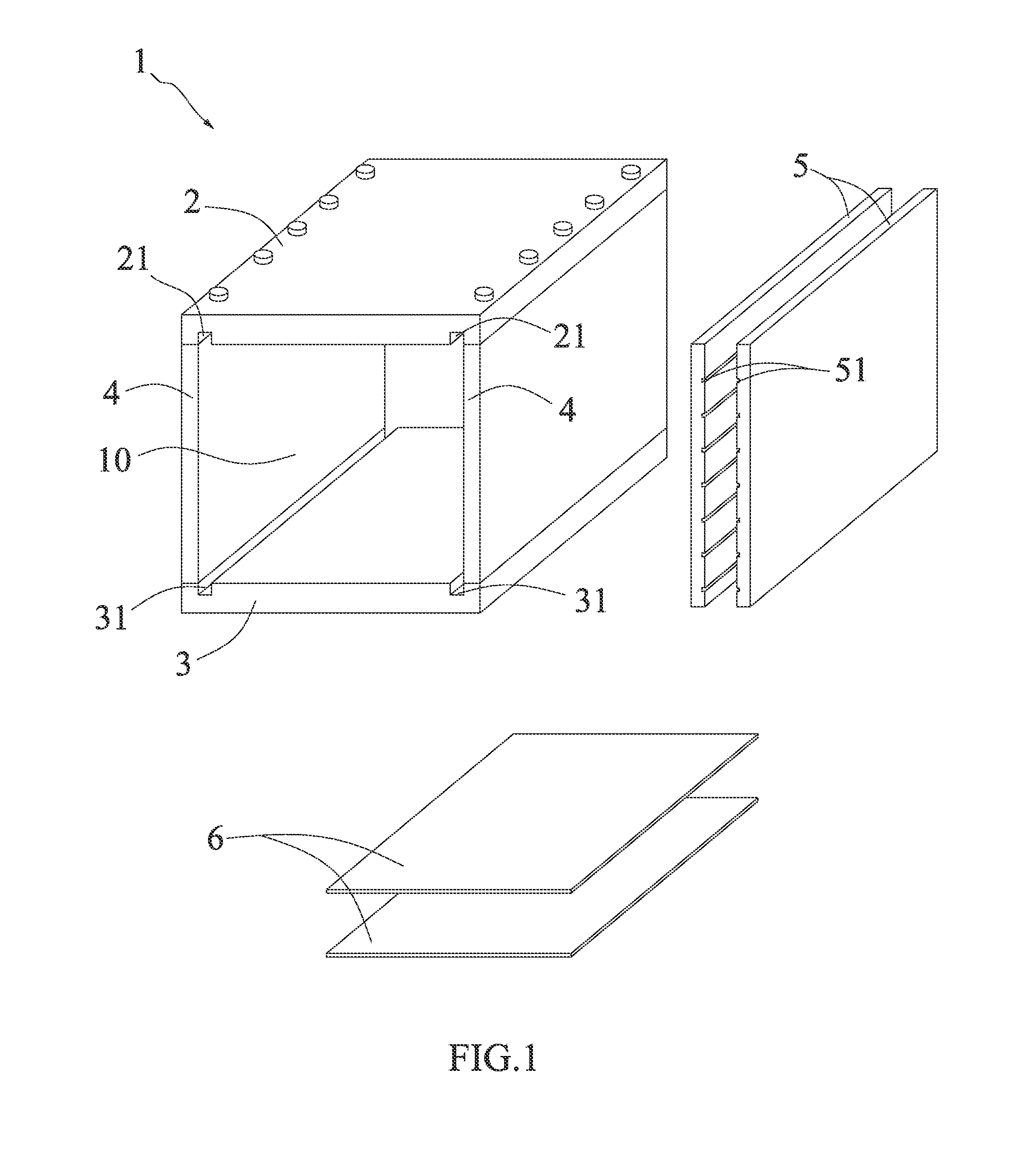
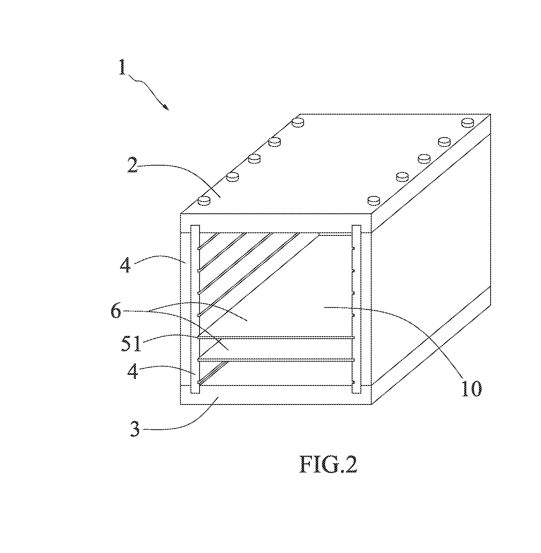
[0016]Referring to FIGS. 1 and 2 illustrating a sintering chamber structure 1 in accordance with the present invention, the sintering chamber structure 1 adapted to store multiple articles (not shown) for being sintered in a sintering furnace (not shown), comprises a first wall, 2, a second wall 3, two side walls 4, a plurality of supporting walls 5, and a plurality of holding boards 6. The first and second walls 2, 3 are disposed opposite to each other horizontally. The two side walls 4 are spaced away vertically each other and interconnect the first and second walls 2. 3 at the end of opposite sides respectively. The two side walls 4 and the first and second walls 2, 3 together define a storage space 10 for communicating outside. The two side walls 4 can be combined with the first and second walls 2, 3 by screws.

[0017]Referring to FIGS. 1 and 2, a pair of positioning slots 21 are formed inwardly at the inner surface of the first wall 2, facing the storage space 10, and spaced away...

second embodiment

[0021]Further referring to FIG. 3 illustrating the present invention, in consideration of the cost management, the supporting wall 5 is capable of being exemplified in several separate parts, which are spaced apart from each other. Each separate part of the supporting wall 5 is provided with the plurality of guiding grooves 51 corresponding to other parts of the supporting wall 5. In this manner, the plurality of holding boards 6 can be inserted in corresponding guiding grooves 51 of the separate parts, whereby the supporting wall 5 can be reduced in size by dividing the internal space into parts so as to lower the cost of manufacturing.

third embodiment

[0022]Referring to FIGS. 4 and 5 illustrating the present invention, the first and second embodiments as mentioned above are known as enclosed structure, that is, each of the two side walls 4 connect the first and second walls 2, 3 and enclose the storage space 10 in a manner such that two opposite ends of each of the side walls 4 are flush with two opposite ends of the first and second walls 2, 3. In the third embodiment, each of the two side walls 4 consists of a plurality of partitions 41, 42 spaced from each other. Likewise, the two side walls 4 in this embodiment are exemplified by the separate partitions 41, 42. Therefore, a total size of the partitions 41, 42 are smaller than the side walls 4 of the first and second embodiments, whereby the cost of manufacturing the side wall 4 can be effectively reduced. Furthermore, the partitions 41, 42 are capable of forming a half enclosed structure with the supporting wall 5.

[0023]Accordingly, the sintering chamber structure 1 of the pr...


PUM


Abstract

A sintering chamber structure adapted to store multiple articles to be sintered in a sintering furnace, includes a first wall, a second wall, two side walls interconnecting the first and second walls, at least two supporting walls, and holding boards for holding the multiple articles. The two side walls and the first and second walls together define a storage space communicating outside. The two supporting walls correspondingly form a plurality of guiding grooves, wherein the first and second walls correspondingly form a pair of positioning slots communicating with the storage space, the at least two supporting walls are detachably inserted in the pairs of positioning slots, respectively, and the holding boards are inserted in corresponding guiding grooves. In this manner, the at least two supporting walls can adjust the inner space according to the sizes of the articles, whereby achieving the best yield of sintering.

Description

BACKGROUND OF THE INVENTION[0001]1. Field of the Invention[0002]The present invention relates to a sintering chamber structure, and particularly to a sintering chamber structure having a detachable structure and being capable of effectively utilizing an internal space of the sintering chamber.[0003]2. Related Art[0004]Metal Powder Injection Molding (MIM) is a new metalworking process utilizing plastic injection molding, polymer and flowable raw material for injection, in combination with powder metallurgy and metal material science. MIM is performed by utilizing finely-powdered metal combined with a measured amount of binder material to produce the raw material (referred to as the feedstock) through mixing and granulating. The feedstock is injected under liquid status into a precise mold by using plastic injection molding machines to form a green part. The green part must have been undergone a process of partially vacuum de-binding to remove a portion of the binder material from the...

Claims


Application Information

Patent Timeline
Patent Type & Authority Applications(United States)
IPC IPC(8): F27D5/00
CPCF27D5/0006
Inventor CHOU, CHENG-YUCHENG, CHIH-WEI
Owner CHENG UEI PRECISION IND CO LTD
Why Eureka
Try Eureka