
Electric Machine Rotor Cooling Method

a technology for electric machines and rotors, applied in the direction of dynamo-electric machines, magnetic circuit rotating parts, magnetic circuit shapes/forms/construction, etc., can solve the problem of not cooling the rotor as effectively as needed

Active Publication Date: 2013-11-28
DEERE & CO
View PDF8 Cites 39 Cited by
  • Summary
  • Abstract
  • Description
  • Claims
  • Application Information

AI Technical Summary

Benefits of technology

This invention provides a way to cool an electric motor by using fluid channels in the rotor and shaft of the motor. The fluid flows through the channels and exits through a radial opening in the rotor. This helps to reduce the temperature of the motor and improve its performance. The method can be used in vehicles that use an electric motor, such as electric cars or bicycles.

Problems solved by technology

The problem with the cooling method of the cited art is that they do not cool the rotor as effectively as needed.

Method used


Image

  • Electric Machine Rotor Cooling Method
  • Electric Machine Rotor Cooling Method
  • Electric Machine Rotor Cooling Method

Examples


Embodiment Construction

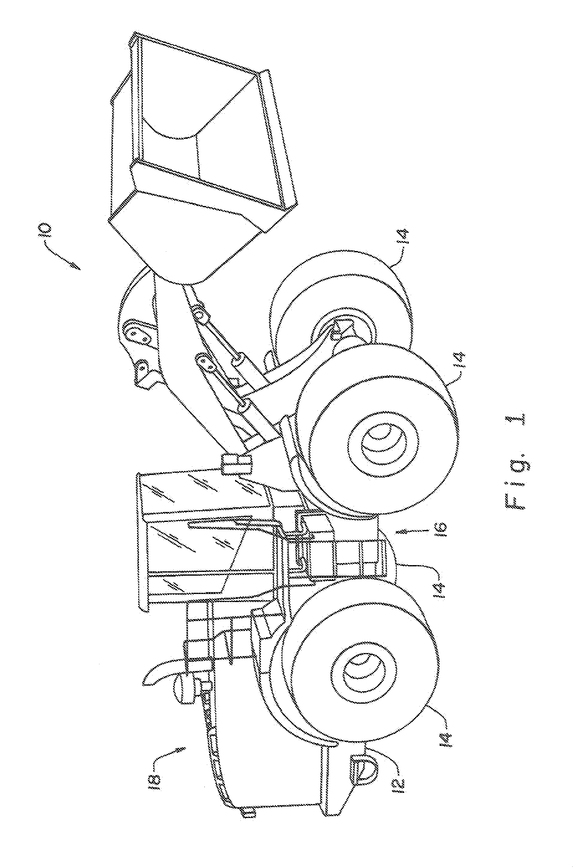
[0017]Referring now to the drawings, and more particularly to FIG. 1, there is illustrated a vehicle 10, which may be in the form of an agricultural machine, a construction machine, a forestry machine or another type of vehicle. Vehicle 10 includes a chassis 12 with ground engaging devices 14 that are either directly or indirectly driven by at least one electric machine, illustrated as an electric motor 16 that is supplied electrical power by way of a power source such as an engine 18 with an electric generator connected thereto. Electrical power from the power source is applied, under the control of the machine operator, to electric motor 16 to drive driven devices 14.

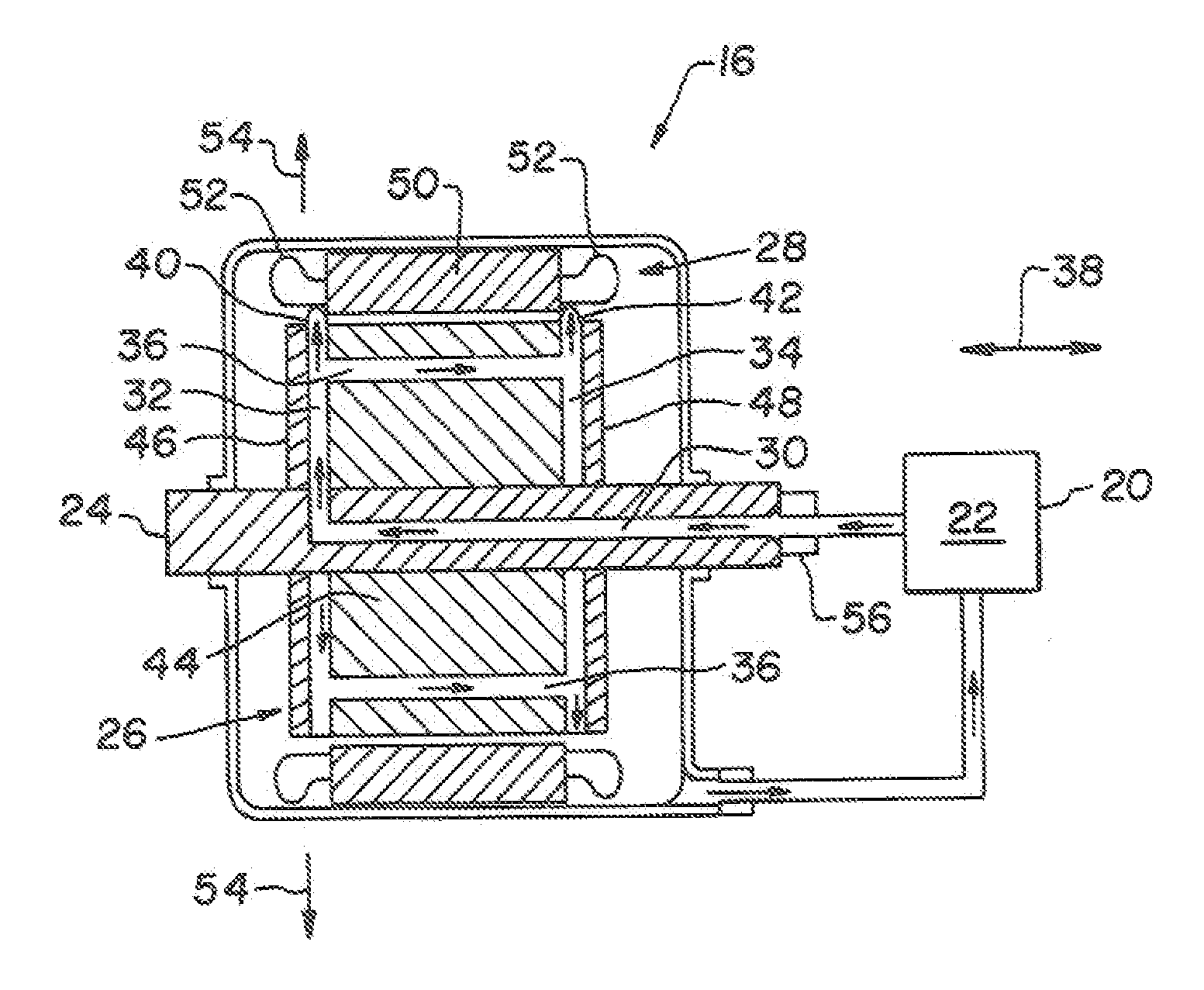
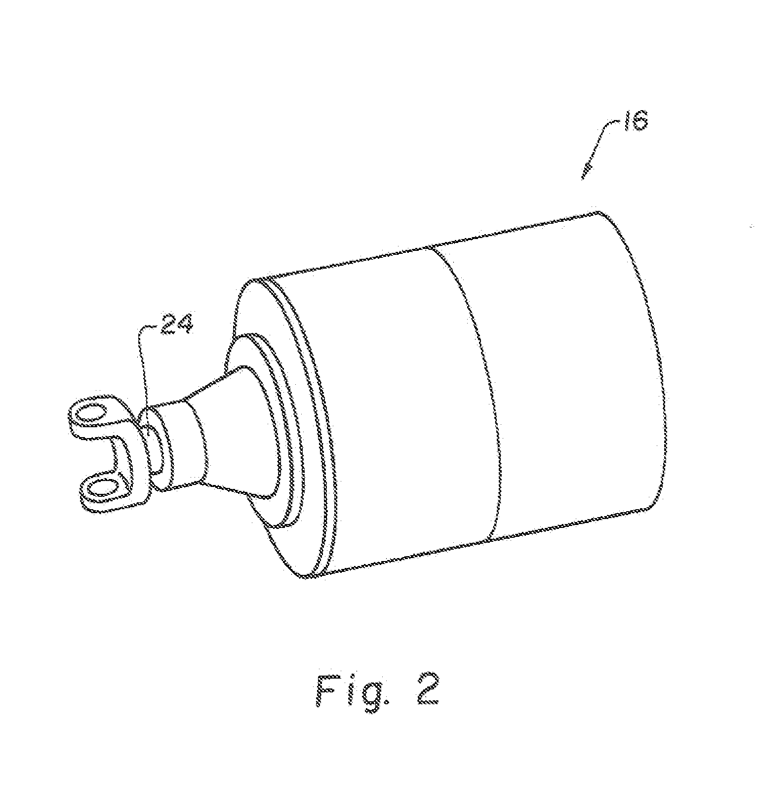
[0018]Now, additionally referring to FIGS. 2 and 3 there is illustrated more detail of electric motor 16, with the electrical connections being omitted for the sake of clarity. Mechanical power from electric motor 16 may be supplemental to a mechanical drive that provides power to driven device 14 or electric motor 16...


PUM


Abstract

An electric motor coupled to a driven device of a vehicle. The electric motor includes a rotor and a shaft coupled to the rotor. The rotor has at least one radially oriented cavity and at least one fluid channel. The fluid channel extends in a generally axial direction. The fluid channel is fluidly connected to the at least one radially oriented cavity. The shaft has a fluid passageway therein. The at least one radially oriented cavity has a fluid connection to the fluid passageway of the shaft. The at least one radially oriented cavity leads to a radial exit from the rotor for a flow of fluid therefrom.

Description

FIELD OF THE INVENTION[0001]The present invention relates to electric motors and generators, and, more particularly, to a method and apparatus for cooling the rotor of an electric machine.BACKGROUND OF THE INVENTION[0002]An electric motor is an electromagnetic / mechanical device that converts electrical energy into mechanical energy. Conversely an electrical generator is an electromagnetic / mechanical device that converts mechanical energy into electrical energy. Electrical machines such as motors and generators operate through the interaction of magnetic fields and current carrying conductors generate the force or electricity respectively. Electric motors are found in applications as diverse as pumps, blowers, fans, machine tools, household appliances, power tools, disc drives in computers and the like. Electrical motors come in various sizes from small motors that are utilized in watches to rather large electric motor / generators utilized in locomotive engines.[0003]A rotor of an ele...

Claims


Application Information

Patent Timeline
IPC IPC(8): H02K9/00
CPCH02K9/005H02K1/32H02K9/19H02K9/00
Inventor MCKINZIE, KYLE K.BROWN, DARYL T.
Owner DEERE & CO
Features
  • Generate Ideas
  • Intellectual Property
  • Life Sciences
  • Materials
  • Tech Scout
  • Unparalleled Data Quality
  • Higher Quality Content
  • 60% Fewer Hallucinations
Learn More