
Lens barrel

a barrel and lens technology, applied in the field of lenses barrels, can solve the problems of limited cam followers, inability to increase the rotational angle of the frame, and the length of the gear, so as to increase the amount of movement of the second frame with respect to the first frame, increase the relative rotational angle, and increase the zoom ratio

Inactive Publication Date: 2013-11-28
PANASONIC CORP
View PDF3 Cites 3 Cited by
  • Summary
  • Abstract
  • Description
  • Claims
  • Application Information

AI Technical Summary

Benefits of technology

The lens barrel described in this patent allows for a larger relative rotational angle between two frames, which results in increased movement of the second frame. This increased movement raises the zoom ratio of the lens.

Problems solved by technology

However, when a gear and a plurality of cam followers are provided to the same frame, the gear is disposed between the cam followers, but with this layout, the length of the gear is limited by the cam followers, so the rotational angle of the frame cannot be increased.

Method used


Image

  • Lens barrel
  • Lens barrel
  • Lens barrel

Examples


Embodiment Construction

[0038]Selected embodiments of the present technology will now be explained with reference to the drawings. It will be apparent to those skilled in the art from this disclosure that the following descriptions of the embodiments of the present technology are provided for illustration only and not for the purpose of limiting the technology as defined by the appended claims and their equivalents.

[0039]

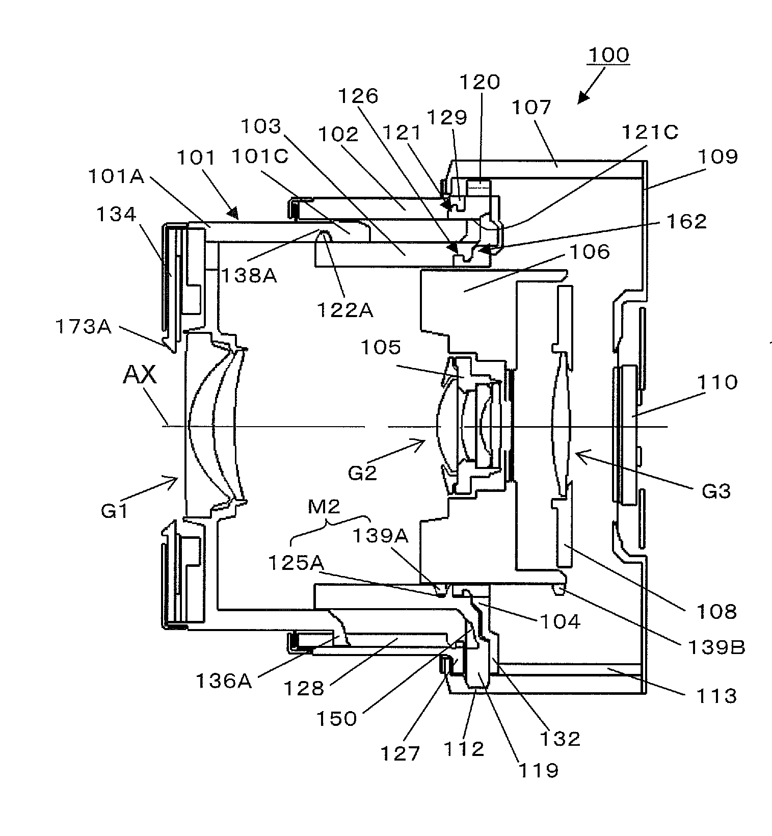
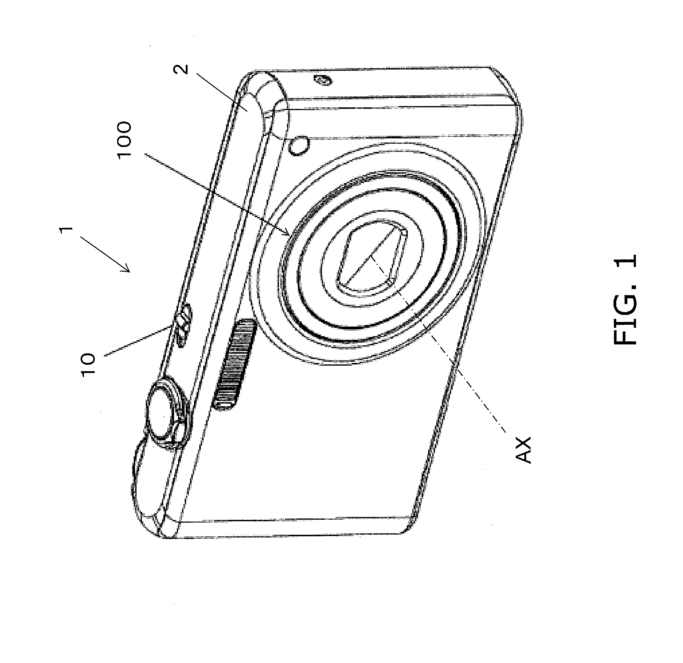
[0040]As shown in FIG. 1, the digital camera 1 comprises a housing 2 and a lens barrel 100 (an example of a lens barrel). When a power switch 10 is used to turn on the power, the lens barrel 100 is deployed from the housing 2 so that imaging is possible.

[0041]The digital camera 1 shown in FIG. 1 is an example of an imaging device. The imaging device may be a digital camera or a film camera. Also, the imaging device may be a camera with which the lens barrel 100 can be removed and exchanged. The imaging device may also be a still camera that primarily captures still pictures. Or, the imagin...


PUM


Abstract

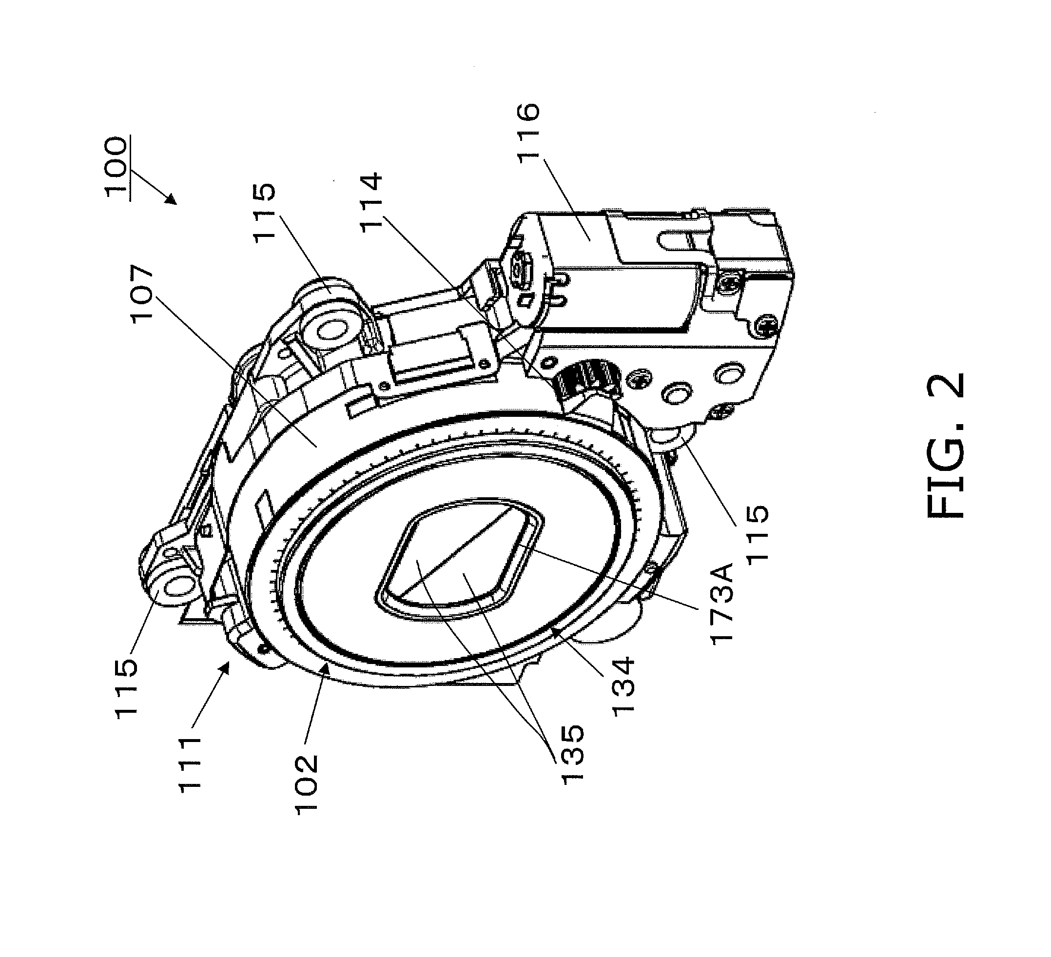
A lens barrel includes a first frame and a second frame. The first frame includes a plurality of cam grooves. The second frame includes a plurality of cam followers that engage with each of the plurality of cam grooves, and a gear portion. In this case, if rotational force is transmitted to the gear portion, the second frame moves in the optical axis direction while rotating with respect to the first frame. At least one of the plurality of cam followers is disposed on the image plane side of the gear portion.

Description

CROSS REFERENCE TO RELATED APPLICATIONS[0001]This is a continuation of PCT Application PCT / JP2012 / 000381, with an international filing date of Jan. 23, 2012 which claims priority to Japanese Patent Application No. 2011-012398 filed on Jan. 24, 2011. The entire disclosures of PCT Application PCT / JP2012 / 000381 and Japanese Patent Application No. 2011-012398 are hereby incorporated herein by reference.BACKGROUND[0002]1. Technical Field[0003]The technology disclosed herein relates to a lens barrel that supports an optical system.[0004]2. Background Information[0005]There are known lens barrels that support an optical system with which the focal distance can be varied. For example, the lens barrel disclosed in Japanese Laid-Open Patent Application 2007-219304 comprises a first moving cam ring in which a cam groove is formed, and a first group lens barrel that supports a first lens group. The first group lens barrel has a follower pin that engages in the cam groove. With this lens barrel,...

Claims


Application Information

Patent Timeline
Patent Type & Authority Applications(United States)
IPC IPC(8): G02B7/04
CPCG02B7/04G02B7/08G02B27/646G02B7/102
Inventor UNO, TETSUYAFUJINAKA, HIROYASU
Owner PANASONIC CORP
Learn More