
Air-type shot-treatment machine

Active Publication Date: 2013-11-28
SINTOKOGIO LTD
View PDF7 Cites 0 Cited by
  • Summary
  • Abstract
  • Description
  • Claims
  • Application Information

AI Technical Summary

Benefits of technology

The present invention allows for a more stable and consistent processing of shots, without the need for frequent changes in conditions. This results in a smaller air-type shot-treatment machine and a simpler machine design.

Problems solved by technology

However, for the air-type shot-treatment machine, when the nozzle ascends and descends, the deformation of a wear-resistant hose connecting the nozzle and a pressurized tank is changed,.Consequently, it causes a problem, such that the conditions of the processing for projecting shots are changed.
However, in such a case, much equipment is required, and the machine becomes large.
However, in such a case, many tanks are required, and piping systems become complicated.
Thus, the entire structure of the machine becomes complicated.

Method used


Image

  • Air-type shot-treatment machine
  • Air-type shot-treatment machine
  • Air-type shot-treatment machine

Examples


Embodiment Construction

[0061]Based on the figures, below an embodiment of this invention is explained.

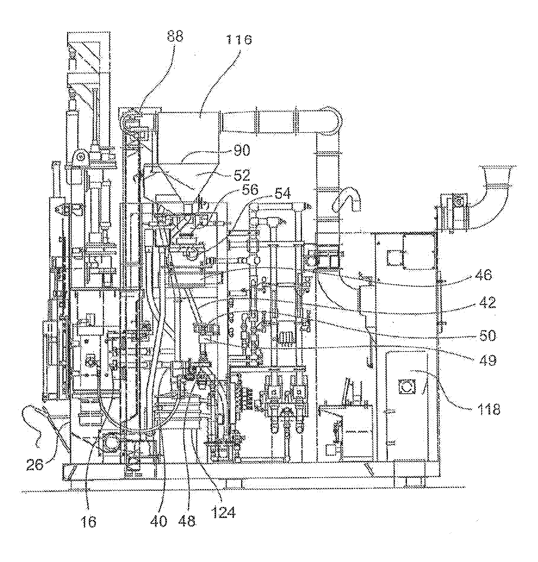
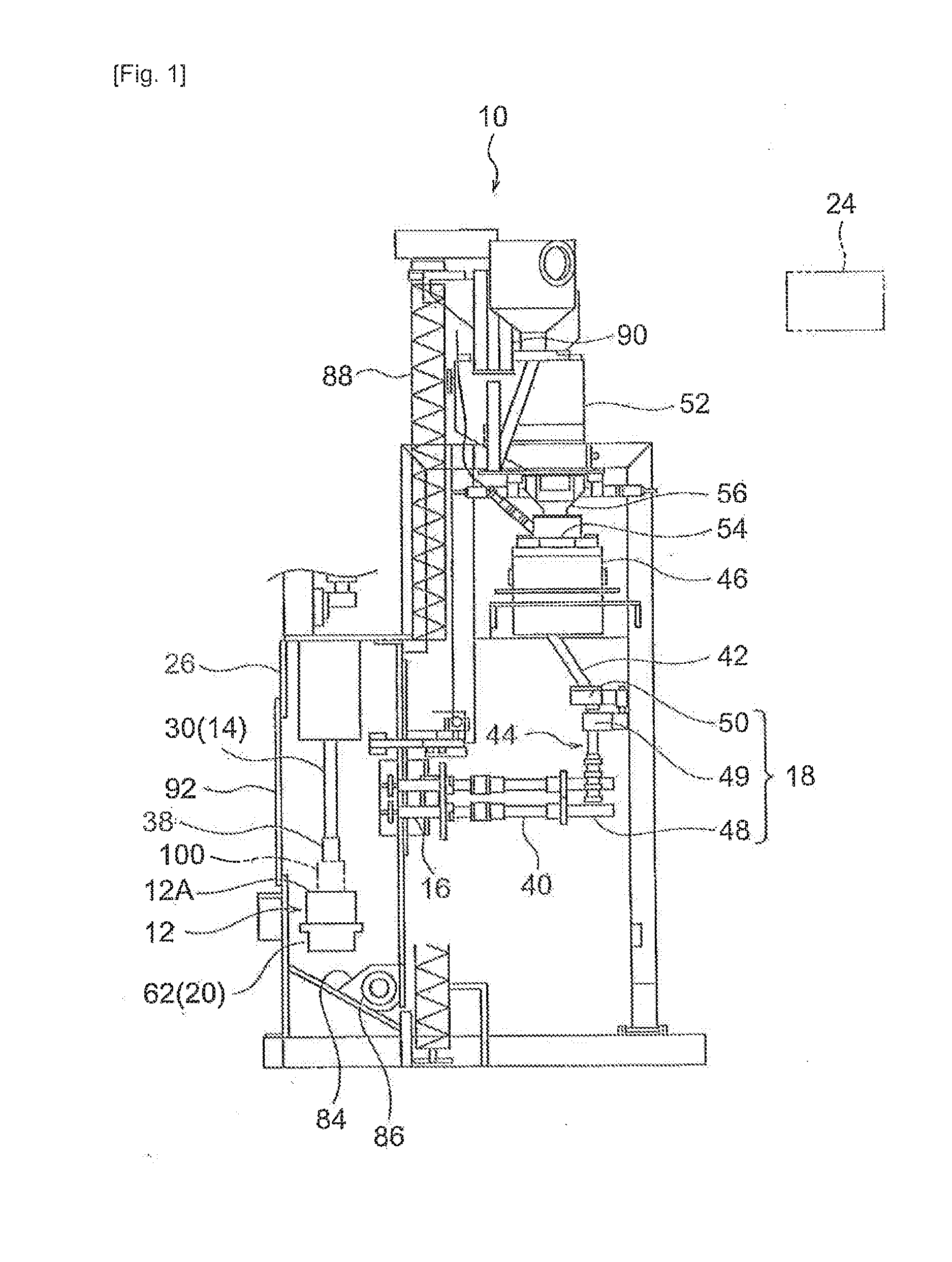
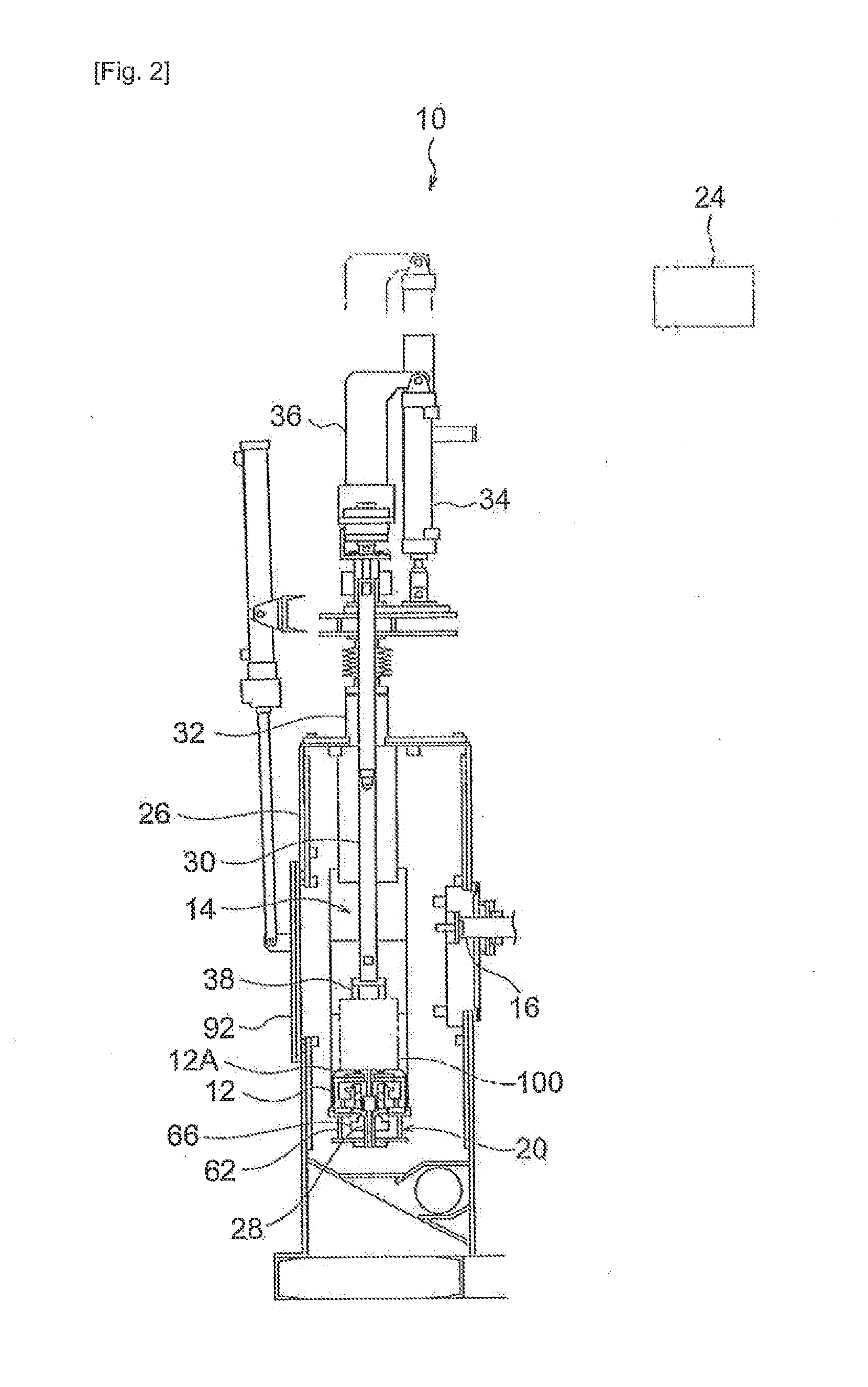
[0062]The air-type shot-treatment machine 10 of an embodiment of this invention, which machine is shown in FIGS. 1-3, is used for shot peening treatment works, for example. The machine 10 comprises a table 12, which acts as a support member, a holding mechanism 14, a nozzle 16, an adjusting device 18 to adjust the quantity of shots, a rotating device 20, a lifting and lowering device 22, which acts as a moving device, a control device 24, and a cabinet 26.

[0063]As shown in FIG. 2, the table 12 is housed in the cabinet 26 and has a rotational shaft 28 disposed on the central axis of the table 12. The rotational shaft 28 extends in the vertical direction and is rotatably supported by a case 62 of the rotating device 20, which device 20 is explained below in detail. The upper surface 12A of the table 12 is formed as a surface for supporting products 100, which are articles to he processed. There are gears of...


PUM

PropertyMeasurementUnit
Speedaaaaaaaaaa

Abstract

The purpose of this invention is to reduce the changes in the conditions of the processing for projecting shots, and to downsize the air-type shot-treatment machine 10 and simplify its structure.An air-type shot-treatment machine 10 comprisesa table 12 to hold an article to he processed, wherein the table 12 can rotate the article and lift and lower it,a nozzle 16 to project shots toward the article together with compressed air, wherein the nozzle 16 is fixed so that it is oriented toward the article, and is connected to a pressurized tank 46 by means of a connecting device 44 having a wear-resistant hose 40, an adjusting device 18 to adjust the quantity of shots projected from the nozzle 16, wherein the adjusting device 18 is disposed at the connecting device 44, a rotating device 20 to rotate the table 12, a moving device 22 to lift and lower the table 12, anda control device 24 to control the adjusting device 18 and the rotating device 20 so that while the table 12 is being rotated, the shots are being projected toward the article to he processed, and, further, to control the moving device 22 so that the table 12 is lifted and lowered.

Description

TECHNICAL FIELD[0001]This invention relates to an air-type shot-treatment machine.BACKGROUND OF THE INVENTION[0002]Conventionally, an air-type shot-treatment machine is used for processing products by projecting shots at them. For example, products that have a plurality of gears coaxially disposed on a shaft with predetermined intervals, or products that have a plurality of gears coaxially disposed on a shaft in contact with each other, are processed by projecting shots while a support member to hold the products and a nozzle for projecting the shots are fixed in position.[0003]However, for such a machine, the support member (to hold the gears) must he changed when the respective gears are replaced and processed. Thus, it takes much time to change the tooling for processing the products.[0004]To solve this problem, an air-type shot-treatment machine having a nozzle that can ascend and descend is provided so as to avoid the change of the tooling being required when the respective gea...

Claims


Application Information

Patent Timeline
IPC IPC(8): B24C3/22B24C1/10
CPCB24C3/22B24C1/10
Inventor YAMAMOTO, MASATOSHI
Owner SINTOKOGIO LTD
Learn More