Downhole fluid transport plunger with thruster

a technology of plunger and plunger, which is applied in the direction of fluid removal, borehole/well accessories, survey, etc., can solve the problems of loss of production, low capital cost, and inability to work with chemical soaping and velocity string, etc., and achieve low maintenance cost and capital cost. low

Active Publication Date: 2013-12-05
SAUDI ARABIAN OIL CO
View PDF3 Cites 20 Cited by
  • Summary
  • Abstract
  • Description
  • Claims
  • Application Information

AI Technical Summary

Benefits of technology

[0009]Applicants have recognized that while plunger lift is a relatively low capital and low maintenance cost artificial lift method, there is a need to find a method of lifting liquids from a wellbore that can take place without shutting in the well for prolonged periods of time. It would also be desirable to find a method of lifting liquids in wells where pressure buildup, alone, is insufficient to push the plunger and liquids to the surface.
[0010]The present invention discloses a new method and apparatus for plunger lift systems to increase gas production as well as increase efficiency in removing liquid loading while allowing the wells to continuously produce through the duration of the method. This invention will minimize or eliminate the need for shutting in the well for prolonged periods of time to build up the pressure necessary to lift the plunger. This invention will allow for as many trips as needed for the plunger to efficiently deliquify gas wells or to remove solid buildup, such as scale and asphaltene, and swab other solid accumulations within the wellbore. Existing passive system methods strictly depend on building up pressure to lift the plunger. Embodiments of this invention instead use a propulsion system, such as a motor driving a propeller, which adds energy to the well fluids and creates the additional pressure difference required to lift the plunger and fluids. This invention can prolong the life of the well beyond what is achievable with current plunger lift systems.

Problems solved by technology

A problem arises when liquids accumulate in the well bore of a gas well.
Liquid loading in the wellbore is often a serious problem especially in mature gas wells.
However when the reservoir pressure declines further, chemical soaping and velocity string may no longer work.
This results in loss of production.
In addition, the procedure may need to be performed multiple times a day, which means that the well would have to be shut on and off multiple times in a 24 hour period, further reducing the hours in a day in which the well can be producing.
If production packers are used to prevent hydrocarbons in the tubing casing annulus, for example as a safety measure, the gas would not be able to accumulate in the annulus above the packers.
Because of the relatively limited space available in the annulus near the bottom of the bore hole, the volume of accumulated gas may not be sufficient to achieve the needed pressure.
In addition, for mature wells with declining production rates, the drop in pressure of the well fluids will reach a point where it's not possible to build up pressure to perform conventional plunger lifting.
Therefore even if wells are shut in, there are also situations where current plunger lift technology will not work.

Method used


Image

  • Downhole fluid transport plunger with thruster
  • Downhole fluid transport plunger with thruster
  • Downhole fluid transport plunger with thruster

Examples


Embodiment Construction

[0028]The present invention will now be described more fully hereinafter with reference to the accompanying drawings, which illustrate various embodiments of the invention. This invention, however, may be embodied in many different forms and should not be construed as limited to the illustrated embodiments set forth herein; rather, these embodiments are provided so that this disclosure will be thorough and complete, and will fully convey the scope of the invention to those skilled in the art. Like numbers refer to like elements throughout.

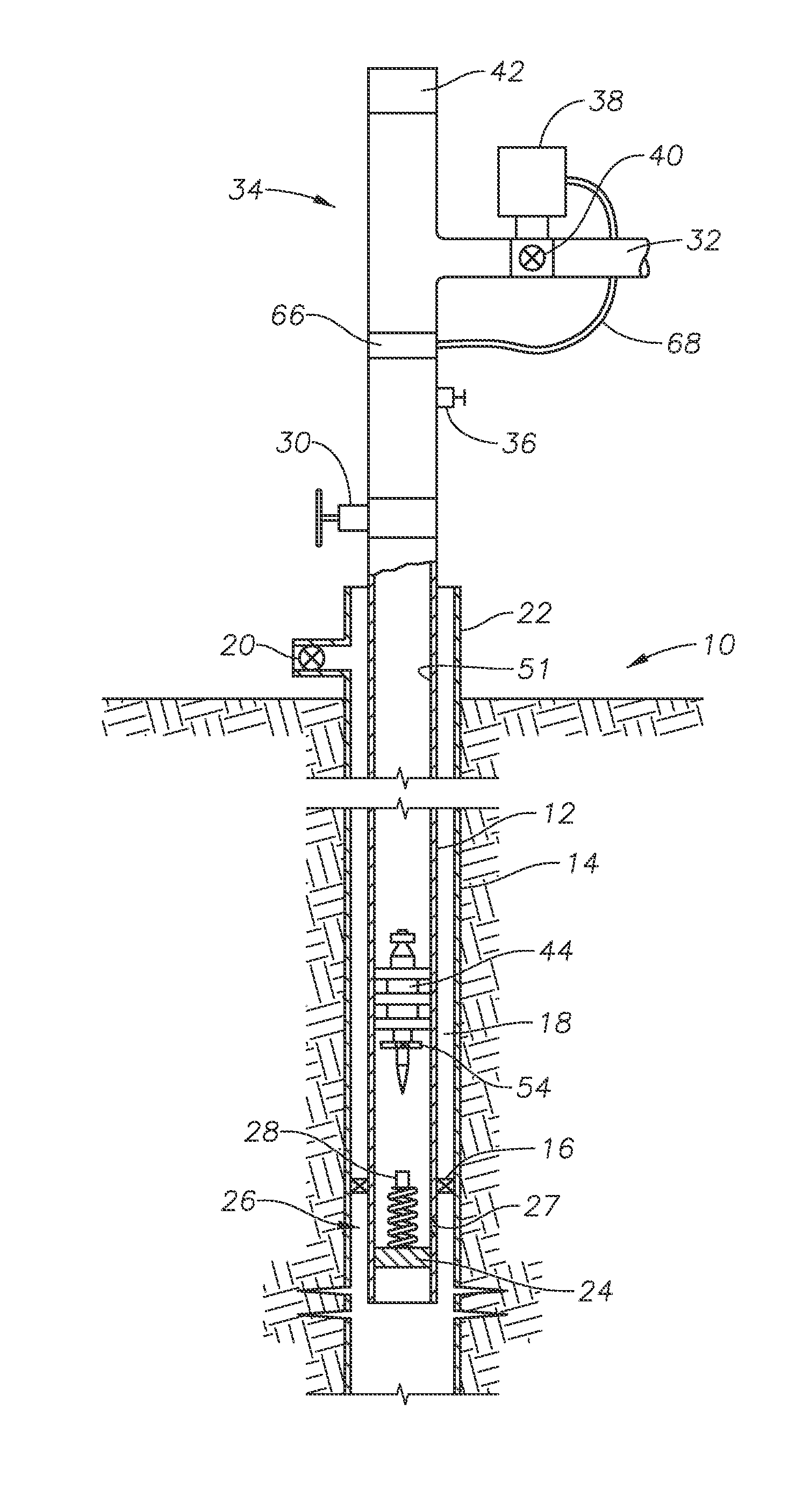
[0029]As seen in FIG. 1, according to an embodiment of the present invention, subterranean well 10 can include production tubing 12 located concentrically within well casing 14. Each of tubing 12 and well casing 14 are considered tubular members. Production packers 16 are sealingly engaged between well casing 14 and production tubing 12 to prevent fluids, such as hydrocarbons, from entering annulus 18 located between an inner surface of well casing...


PUM


Abstract

A method for lifting fluids within a subterranean well includes lowering an elongated plunger to a lower region of a bore of the subterranean well. The plunger includes a motor assembly operably connected to a propeller. A seal can be created between the plunger and an inner surface of the bore of the subterranean well. A thruster, such as motor assembly connected to a propeller, generates thrust to lift the plunger to a plunger retainer located proximate to a wellhead of the subterranean well.

Description

PRIORITY CLAIM[0001]This application claims priority to U.S. Provisional Patent Application No. 61 / 655,745 titled “Downhole Fluid Transport Plunger with Motor and Propeller,” filed on Jun. 5, 2012, the disclosure of which is incorporated herein by reference in its entirety.BACKGROUND OF THE INVENTION[0002]1. Field of the Invention[0003]The general field of the invention is artificial lift, in particular, plunger lift systems to move liquids upward in a subterranean well.[0004]2. Description of the Related Art[0005]Subterranean wells typically produce both liquids and gasses. Gas wells will therefore produce liquids, such as fresh water, salt water, or condensate, with the gas flow. A problem arises when liquids accumulate in the well bore of a gas well. The liquids in the wellbore will hold back and eventually stop the flow of gas to the wellbore and therefore stop production of gas to the surface. This is known as liquid loading. Liquid loading in the wellbore is often a serious pr...

Claims


Application Information

Patent Timeline
Patent Type & Authority Applications(United States)
IPC IPC(8): E21B43/12
CPCE21B43/121
Inventor XIAO, JINJIANGSAEED, ABUBAKER
Owner SAUDI ARABIAN OIL CO
Why Eureka
Try Eureka