

Ultrasound-based localization of client devices in distributed communication systems, and related devices, systems, and methods
a distributed communication system and client device technology, applied in direction finders, direction finders using ultrasonic/sonic/infrasonic waves, instruments, etc., can solve the problems of weak gps signals, other services may be negatively affected or not possible, and techniques such as global positioning services (gps) may not be effective at providing or determining the location of client devices
- Summary
- Abstract
- Description
- Claims
- Application Information
AI Technical Summary
Benefits of technology
Problems solved by technology
Method used
Image

Examples
Embodiment Construction
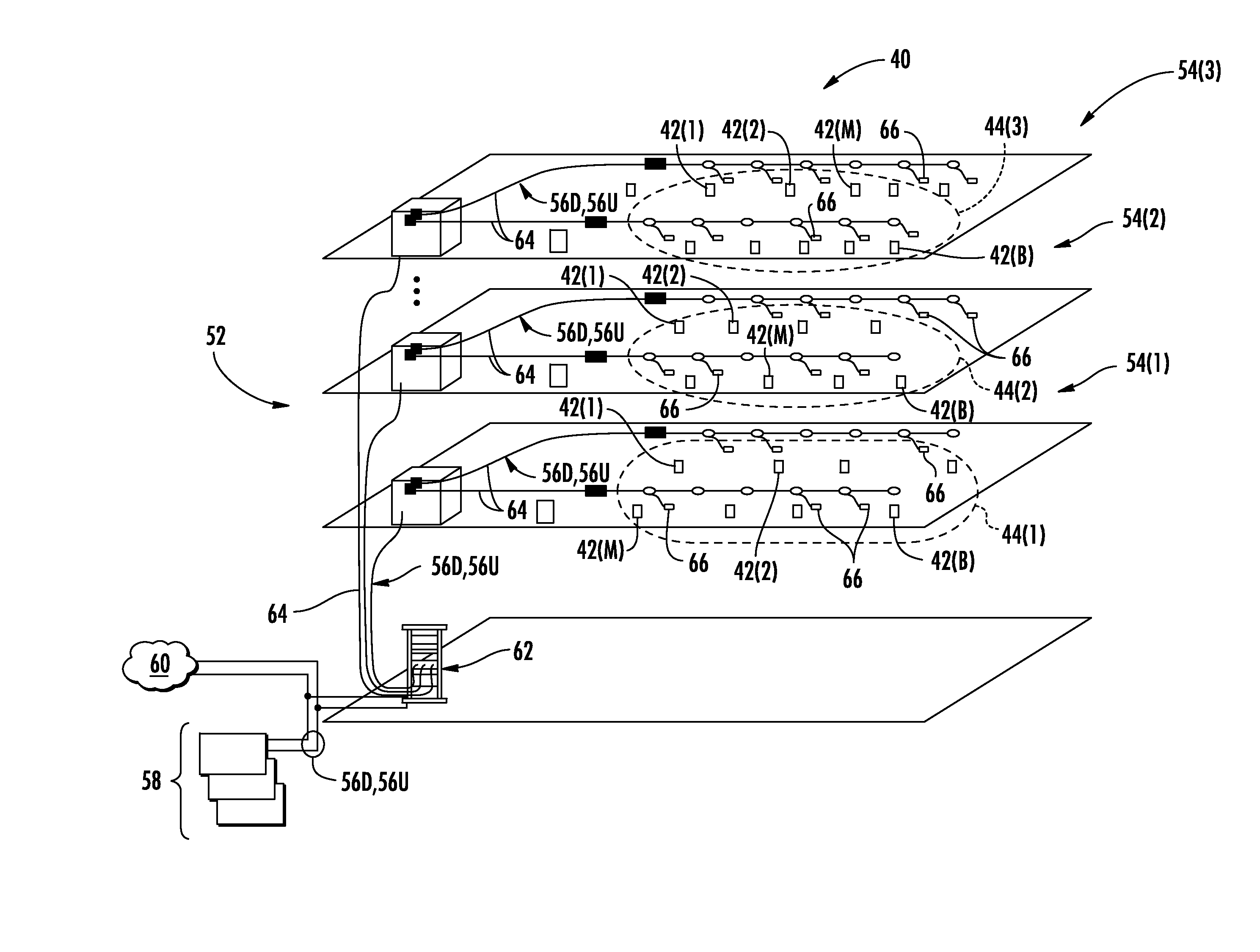
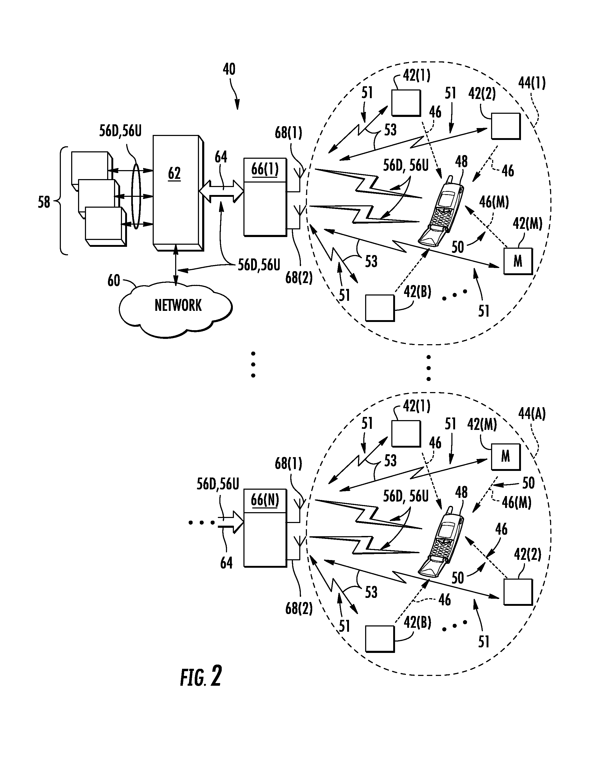
[0013]Embodiments disclosed herein include ultrasound-based localization of client devices in distributed communications systems, as well as elated devices, systems, and methods. In this regard in embodiments disclosed herein, a plurality of spatially located ultrasound beacons are provided in known locations within the distributed communications systems. Each of the spatially located ultrasound beacons is configured to emit ultrasound pulses that can be received by client devices in ultrasound communication range of the ultrasound beacons. The client devices are configured to analyze the received ultrasound pulses from the plurality of ultrasound beacons to determine their time-difference of arrivals at the client device. As a result, the client devices can determine their relative distance to ultrasound beacons in a distributed communications system. In certain embodiments, a master ultrasound beacon is provided that encodes location information in a second channel with emitted ul...
PUM
 Abstract
Description
Claims
Application Information