Mouth opening instrument and method

a technology of mouth opening and mouth, which is applied in the field of mouth opening instruments, can solve the problems of increasing lower members, distressing patients, and difficulty in patient's mouth closing, and achieves the effects of reducing the closing resistance of the upper member and the lower member, and reducing the patient's discomfor

Inactive Publication Date: 2013-12-05
KYUSHU UNIV +1
View PDF5 Cites 12 Cited by
  • Summary
  • Abstract
  • Description
  • Claims
  • Application Information

AI Technical Summary

Benefits of technology

[0008]In the mouth opening instrument according to the exemplary embodiment, when the certain operating state is inputted into the input section, the closing resistance of the upper member and the lower member is increased, making it difficult for the patient's mouth to close. Therefore, dental treatmen

Problems solved by technology

Therefore, the patient experiences distress, such as from not being able to swallow saliva.
In the mouth opening instrument according to the exemplary embodiment, when the certain op

Method used


Image

  • Mouth opening instrument and method
  • Mouth opening instrument and method
  • Mouth opening instrument and method

Examples


first embodiment

[0019]A mouth opening instrument and a dental treatment system including the mouth opening instrument according to a first embodiment of the present invention will hereinafter be described with reference to FIG. 1 to FIG. 5.

[Configurations of the Mouth Opening Instrument and the Dental Treatment System]

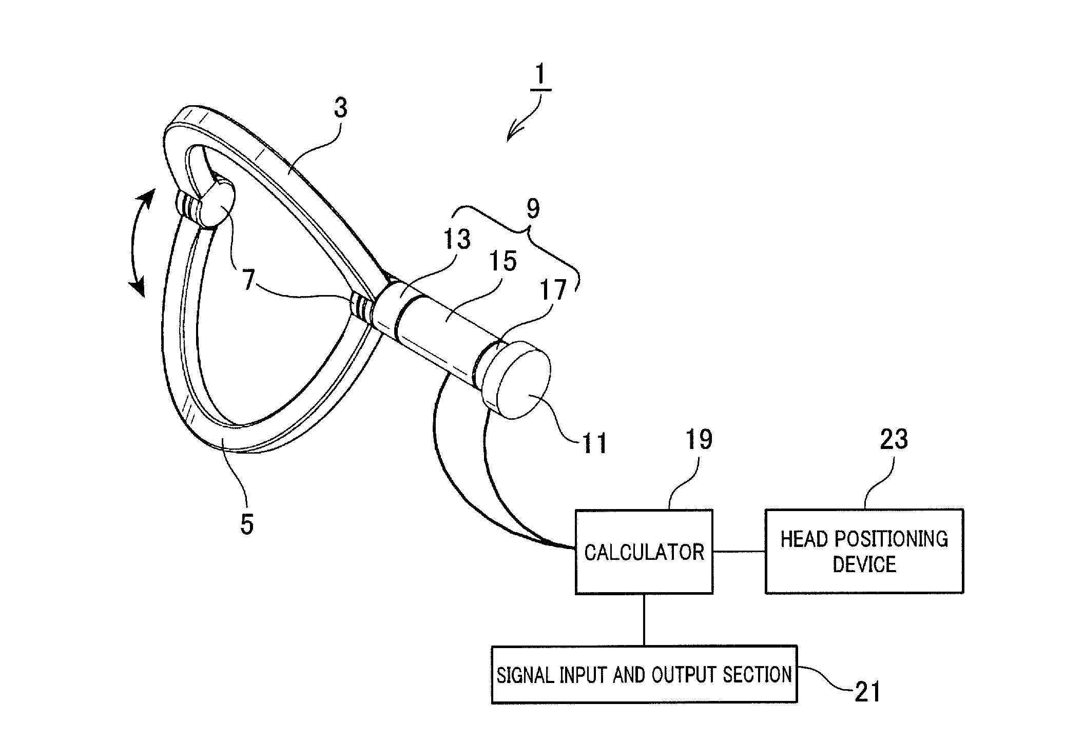
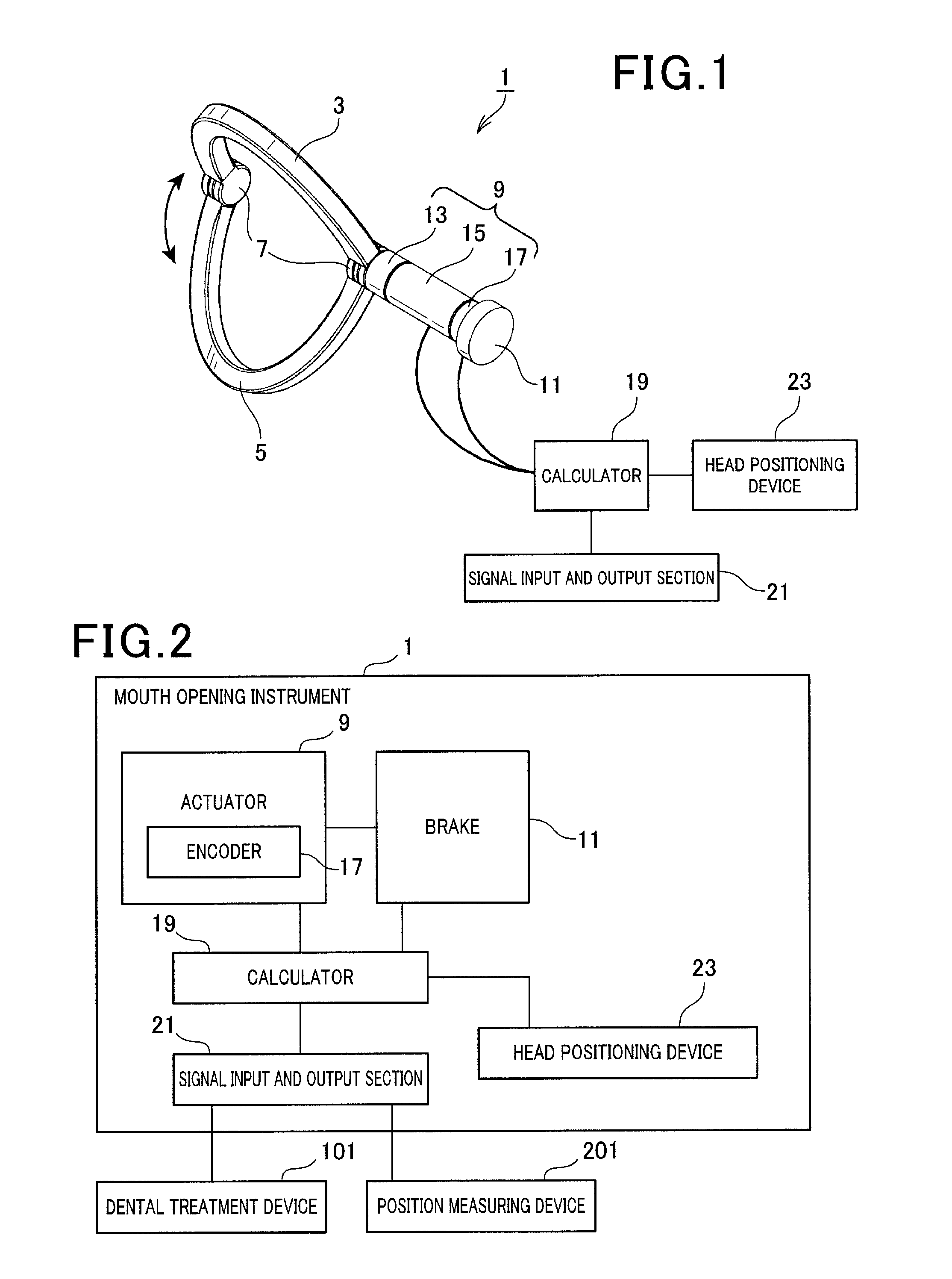
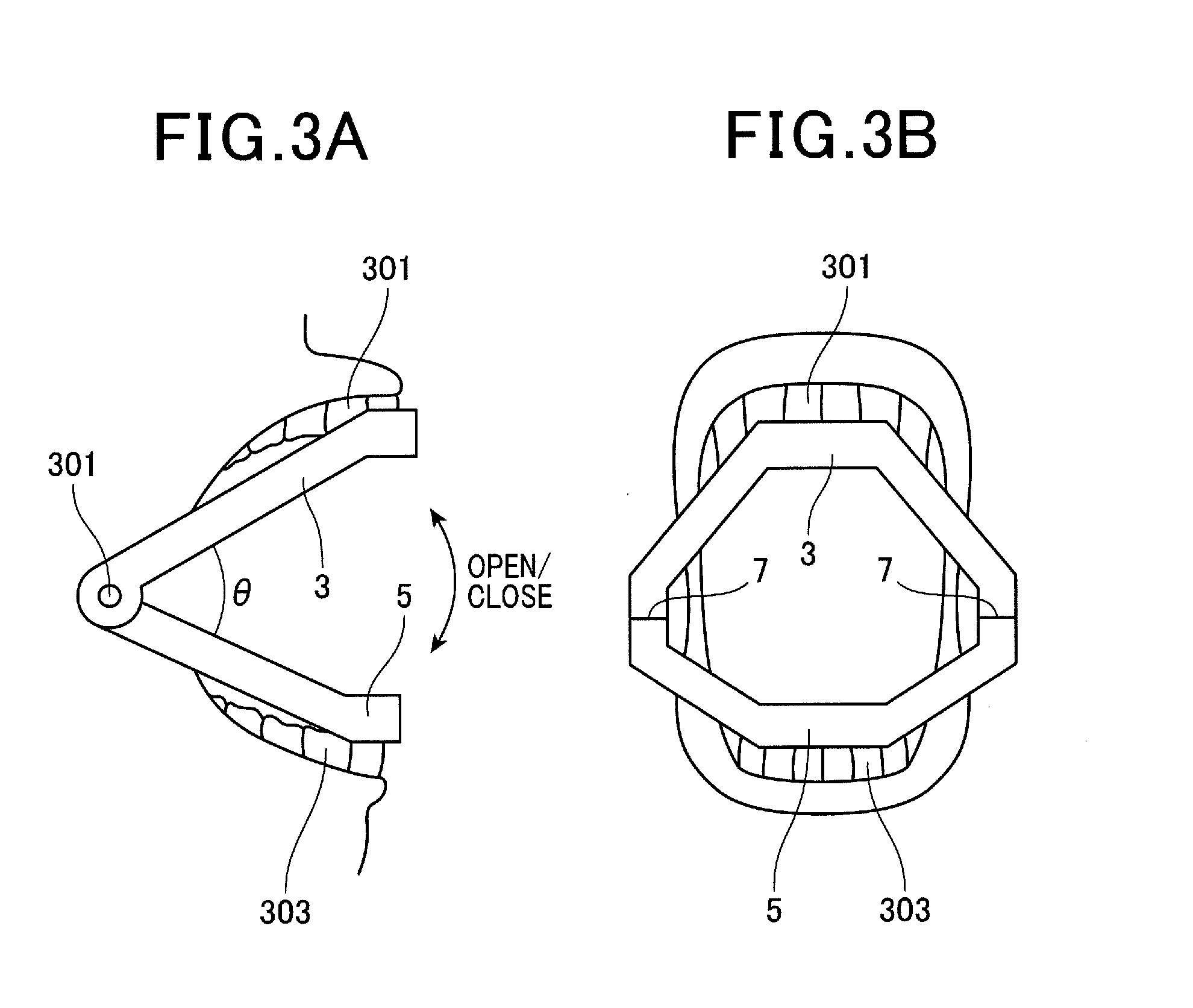
[0020]FIG. 1 is a configuration diagram of a mouth opening instrument 1 according to the first embodiment. FIG. 2 is a block diagram of an electrical circuit of the mouth opening instrument 1 and a configuration diagram of a dental treatment system including the mouth opening instrument 1. FIG. 3A and FIG. 3B are diagrams of a method of use of the mouth opening instrument 1, in which FIG. 3A is a side view and FIG. 3B is a front view.

[0021]As shown in FIG. 1, the mouth opening instrument 1 includes an actuator 9 that rotates an upper member 3 and a lower member 5. The actuator 9 is configured by a motor 15, an encoder 17, and a decelerator 13. Specifically, the rotational force of the...

second embodiment

[0057]A mouth opening instrument according to a second embodiment of the present invention will hereinafter be described.

[Configuration of the Mouth Opening Instrument]

[0058]A configuration of a mouth opening instrument 1′ according to a second embodiment will be described with reference to FIG. 8 and FIG. 9. In FIG. 8 and FIG. 9, components that are similar to those according to the first embodiment are given the same reference numbers. The configuration of the mouth opening instrument 1′ is similar to that of the mouth opening instrument 1 according to the first embodiment. However, the mouth opening instrument 1′ differs in that the head positioning device 23 according to the first embodiment is not included, and the structure of an actuator 9 according to the second embodiment differs from that of the actuator 9 according to the first embodiment. The mouth opening instrument 1′ will be described mainly focusing on the differences. Descriptions regarding sections similar to those...


PUM


Abstract

A mouth opening instrument includes an upper member suitable for attaching on an upper jaw side within the mouth of a patient and a lower member suitable for attaching on a lower jaw side. The instrument further includes a connecting section, a control section, and an input section. The connecting section connects end portions of the upper member and the lower member such that a resistance of opening or closing actions of the upper member and the lower member are controllable. The control section controls the resistance of opening or closing actions of the upper member and the lower member. The input section receives an operating state signal indicating an operating state of a dental treatment device. When the operating state signal indicating an operating state of a dental treatment device is inputted, the closing resistance of the upper member and the lower member is set to be greater than that at a time when the operating state signal is not inputted.

Description

CROSS-REFERENCE TO RELATED APPLICATION[0001]This application is based on and claims the benefit of priorities from earlier Japanese Patent Application No. 2012-127057 filed Jun. 4, 2012, the description of which is incorporated herein by reference.BACKGROUND OF THE INVENTION[0002]1. Technical Field[0003]The present invention relates to a mouth opening instrument used, for example, in dental treatment.[0004]2. Description of the Related Art[0005]A patient's mouth is required to be kept open during dental treatment. Therefore, a mouth opening instrument that is set between the upper and lower teeth of the patient, such as that described in JP-A-2007-282698, is proposed.[0006]When the mouth opening instrument described in JP-A-2007-282698 is used, the patient's mouth is kept open at all times regardless of the circumstances during the dental treatment. Therefore, the patient experiences distress, such as from not being able to swallow saliva. Thus, a mouth opening instrument is desired...

Claims


Application Information

Patent Timeline
IPC IPC(8): A61C5/00A61C19/04
CPCA61C5/007A61C19/04A61B1/24A61C1/082A61B2034/2055A61C5/90
Inventor OKUDA, HIDEKIKOYAMA, TOSHIHIKOIKEGAMI, TATSUYAHASHIZUME, MAKOTOOUCHIDA, RIICHITOYODA, KAZUTAKACHO, BYUNGHYUN
Owner KYUSHU UNIV
Why Eureka
Try Eureka