
Micro matrix data marking

The creation of micro matrix markings on objects using surface alterations and advanced reading systems addresses size and compatibility issues, achieving high data density and biocompatibility for medical and industrial applications.

Inactive Publication Date: 2013-12-12
TRIUNE IP
View PDF7 Cites 0 Cited by
  • Summary
  • Abstract
  • Description
  • Claims
  • Application Information

AI Technical Summary

Benefits of technology

This approach results in improved micro matrix data marking clarity, increased data capacity, and biocompatibility, suitable for small implantable medical devices and various industrial applications, with reduced marking size and enhanced readability.

Problems solved by technology

Thus, the present state of the art presents problems in terms not only of matrix data marking size, but also other physical characteristics.

Method used


Image

  • Micro matrix data marking
  • Micro matrix data marking
  • Micro matrix data marking

Examples


Embodiment Construction

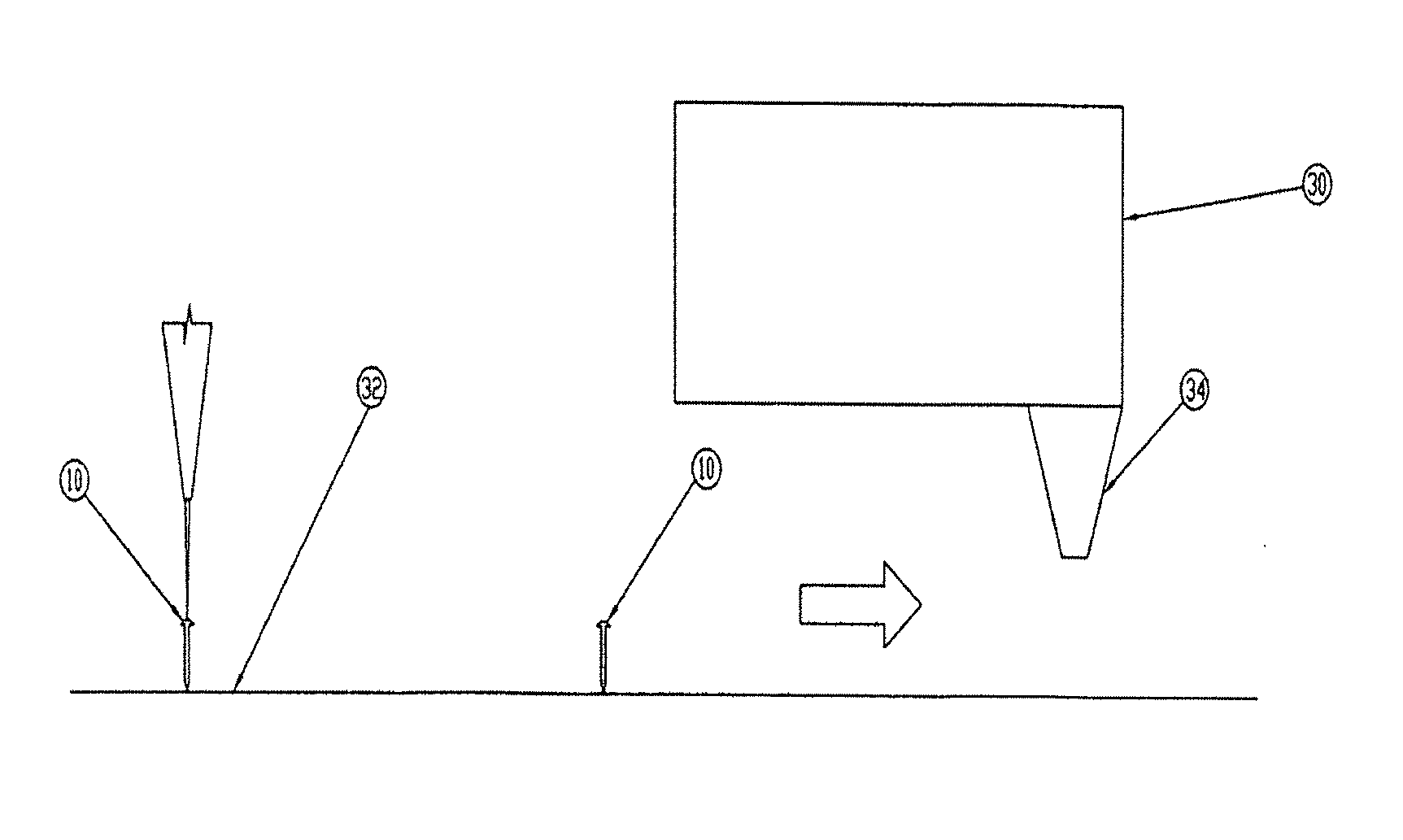
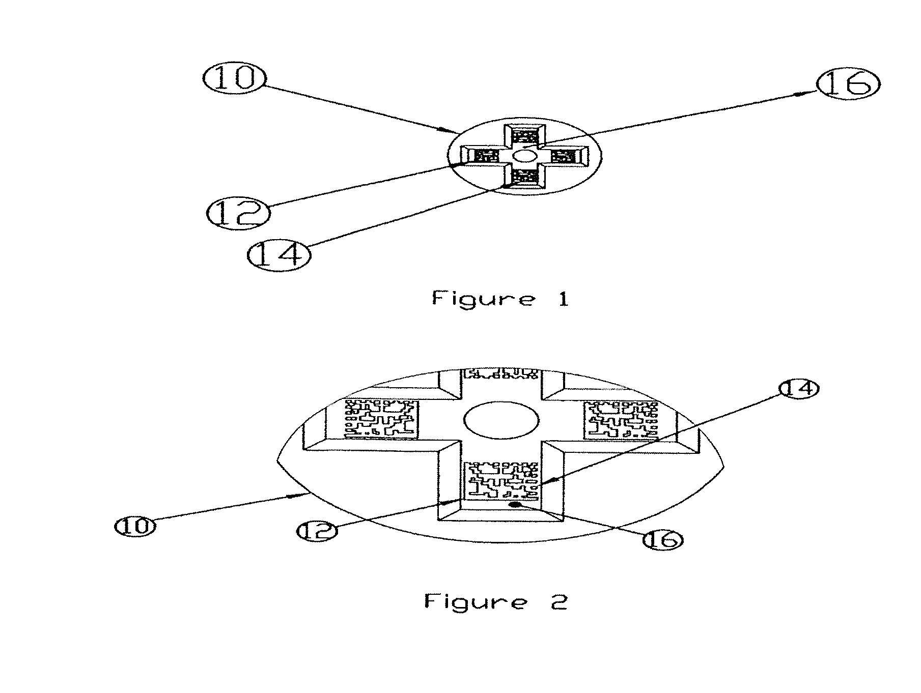
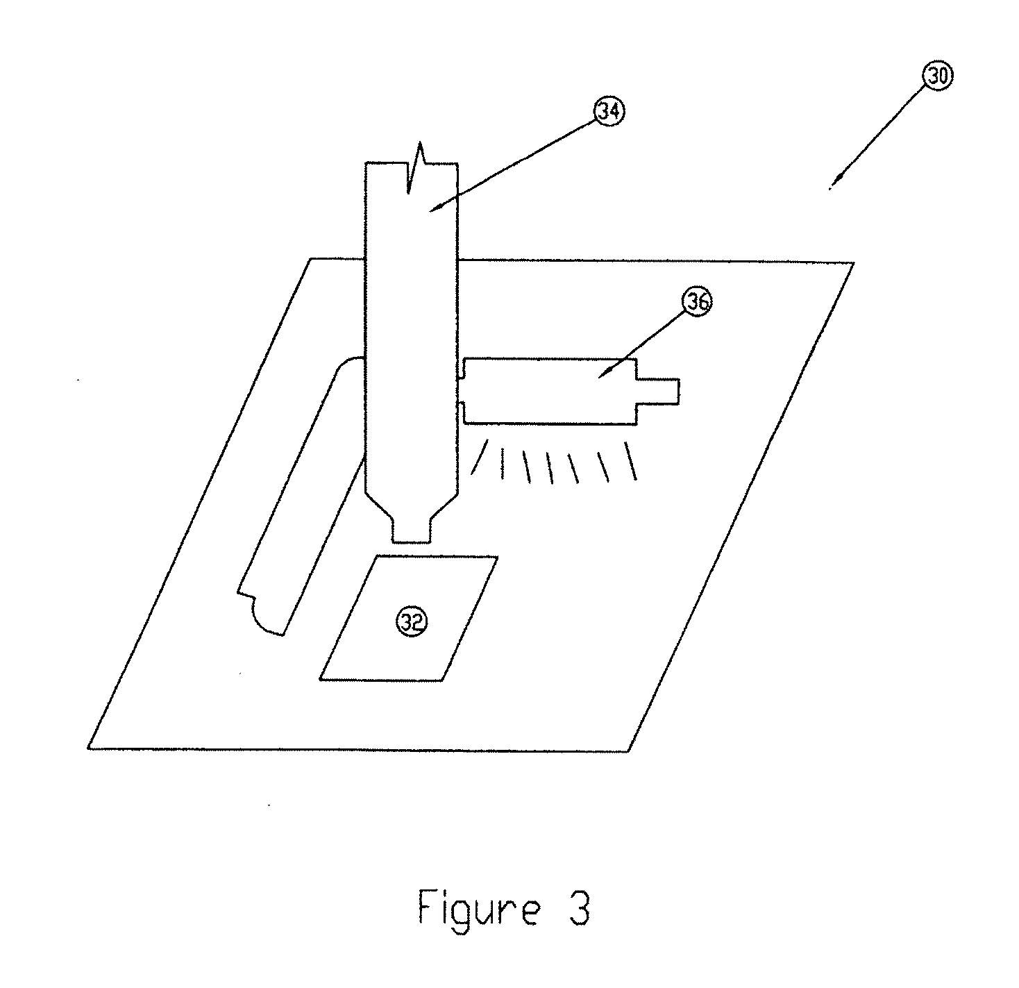
[0032]Micro matrix data markings for objects, for example, very small objects such as implantable screws and other components are reduced in size beyond existing standards as described. Reduction in micro matrix marking cell size in turn leads to reduced matrix size, increased data density, or both. While the making and using of various exemplary embodiments of the invention are discussed herein, it should be appreciated that the present invention provides inventive concepts which can be embodied in a wide variety of specific contexts. It should be understood that the invention may be practiced with various manufactured products and physical articles having markable surfaces, such as for example, microelectronic circuits, mechanical parts, natural objects, projectiles, medical devices, and medication, without altering the principles of the invention. For purposes of clarity, detailed descriptions of functions, components, and systems familiar to those skilled in the applicable arts ...


PUM


Abstract

The invention provides methods and systems for the application and reading of micro markings for coding of information for placement on the surfaces of individual very small devices. In preferred embodiments, a two dimensional micro matrix of markings or dots is realized on a scale of a 25 um cell size and smaller.

Description

RELATED APPLICATIONS[0001]This application is a continuation of U.S. patent application Ser. No. 12 / 646,509 filed Dec. 23, 2009, which claims the priority benefit under 35 U.S.C. §119(e) of U.S. Provisional Patent Application Ser. No. 61 / 140,608 filed Dec. 23, 2008, the entire disclosures of which are incorporated herein by reference.TECHNICAL FIELD[0002]The invention relates to marking objects with data such as part identification or serialization data. More particularly, the invention relates to micro markings, and micro marking and reading systems and methods for providing and using micrometer scale encoded data on manufactured goods and other articles.BACKGROUND OF THE INVENTION[0003]Commercial product marking standards exist in industries such as automotive, defense, medical, and electronics in applications where traceability is considered desirable. These standards are part of endeavors to ensure that traceable identifying marks are suitable for process control in the relevant...

Claims


Application Information

Patent Timeline
Patent Type & Authority Applications(United States)
IPC IPC(8): G06K1/12
CPCG06K1/12G06K1/125G06K1/128B41M5/24G06K1/04G06K19/06037G06K19/06187
Inventor TEGGATZ, ROSS E.BLACKALL, ERIC
Owner TRIUNE IP
Learn More