Machining center

a technology of machining center and machining center, which is applied in the direction of manufacturing tools, metal-working machine components, positioning apparatuses, etc., can solve the problems of affecting the stability of the machine, the height of the machining center is easily increased,

Active Publication Date: 2013-12-12
MAKINO MILLING MASCH CO LTD
View PDF11 Cites 14 Cited by
  • Summary
  • Abstract
  • Description
  • Claims
  • Application Information

AI Technical Summary

Benefits of technology

[0006]The machining center according to the present invention includes: a spindle to which a tool is attached in a detachable manner; a tool magazine provided in a tilted posture above a work space facing the spindle so that a side of the spindle becomes lower, the tool magazine being rotatable and indexable and having a plurality of tool holding parts for holding tools changed with the spindle in a circumferential direction; a shutter arranged in an openable and closable manner at a boundary part of the tool magazine and the work space; a rotation drive unit rotating the tool magazine; an opening and closing drive unit opening closing the shutter; and a control unit controlling the rotation drive unit and the opening and closing drive unit, wherein the tool magazine has a tool-free area in which there are no tool holding parts at a part of the circumferential direction and a tool-holding area in which there are tool holding parts at another part of the circumferential direction, and the control unit controls the rotation drive unit and the opening and closing drive unit so that when the shutter is open, the tool-holding area moves to the side of the spindle and so that when the tool-free area moves to the side of the spindle side, the shutter closes.

Problems solved by technology

For this reason, the machining center easily becomes much higher in overall height and the stability of the machine is impaired.

Method used


Image

  • Machining center
  • Machining center
  • Machining center

Examples


Embodiment Construction

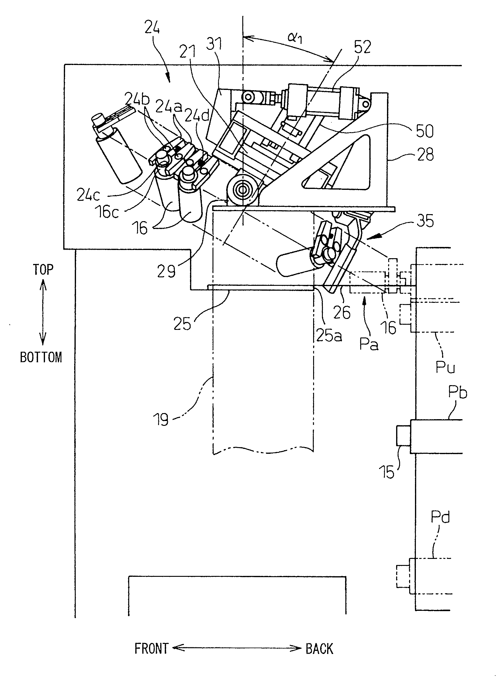
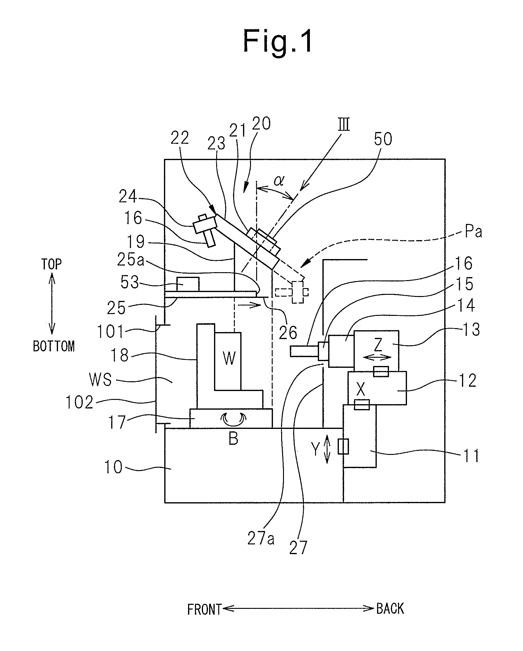
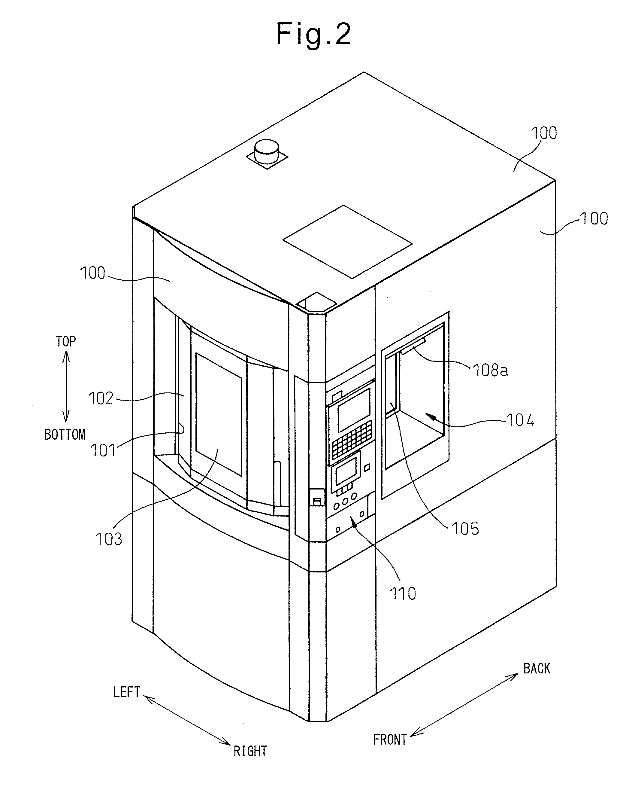
[0019]Hereinafter, referring to FIG. 1 to FIG. 12, an embodiment of a machining center according to the present invention will be explained. FIG. 1 is a side view which shows the schematic configuration of the machining center according to the embodiment of the present invention, while FIG. 2 is a perspective view of the appearance of this machining center. Below, as illustrated for convenience, a front-back direction, left-right direction, and up-down direction are defined and the configurations of the parts are explained in accordance with these definitions.

[0020]As shown in FIG. 1, at the back surface of bed 10, an up-down movement member 11 is supported movably in the up-down direction (Y-axis direction) through a linear feed mechanism. At the top surface of the up-down movement member 11, a left-right movement member 12 is supported movably in the left-right direction (X-axis direction) through a linear feed mechanism. At the top surface of the left-right movement member 12, a ...


PUM


Abstract

A machining center includes a rotatable tool magazine (22) arranged above a work space (WS) facing a spindle (15) tilted so that the spindle side becomes lower and having a plurality of grippers (24) for holding tools (16) in a circumferential direction, and a shutter (26) arranged below the tool magazine (22) to be able to open and close facing the spindle side. The tool magazine (22) has a tool-free area (AR2) where there are no grippers (24) at a part of the circumferential direction and a tool-holding area (ARA) where there are grippers (24) at another part of the circumferential direction. The tool magazine (22) is controlled in rotation so that when the shutter (26) is closed, the tool-free area (AR2) moves to the spindle side while when the shutter (26) is open, the tool-holding area (AR1) moves to the spindle side.

Description

REFERENCE TO RELATED APPLICATIONS[0001]This application is the national stage application under 35 USC 371 of International Application No. PCT / JP2011 / 054824, filed Feb. 24, 2011, the entire contents of which are incorporated herein by reference.FIELD OF THE INVENTION[0002]The present invention relates to a machining center which has an automatic tool changing function.BACKGROUND OF THE INVENTION[0003]There is a known machining center, in which a tool magazine is attached above a work space in a rotatable manner and tools are automatically changed between the tool magazine and a spindle (for example, see Patent Literature 1). The machining center described in this PLT 1 is provided at the front of the spindle with a door which can open and close facing the work space for carrying out the work of changing workpieces in the work space. Furthermore, in order to facilitate the workpiece changing work, etc., the tool magazine is provided tilted so that the door side becomes higher and th...

Claims


Application Information

Patent Timeline
Patent Type & Authority Applications(United States)
IPC IPC(8): B23Q3/155
CPCB23Q3/15526B23Q3/15533B23Q3/15706B23Q11/08B23Q3/15722Y10T483/115Y10T483/1743Y10T483/179Y10T483/1795Y10T483/1882B23Q11/0891
Inventor KOIKE, SHINJINAKAYASU, KAZUMASAYAMAGUCHI, YOSHITAKA
Owner MAKINO MILLING MASCH CO LTD
Why Eureka
Try Eureka