

Rotor balance device for laser removal and method thereof
- Summary
- Abstract
- Description
- Claims
- Application Information
AI Technical Summary
Benefits of technology
Problems solved by technology
Method used
Image

Examples
Embodiment Construction
[0031]The above objectives and structural and functional features of the present invention will be described in more detail with reference to preferred embodiments thereof shown in the accompanying drawings
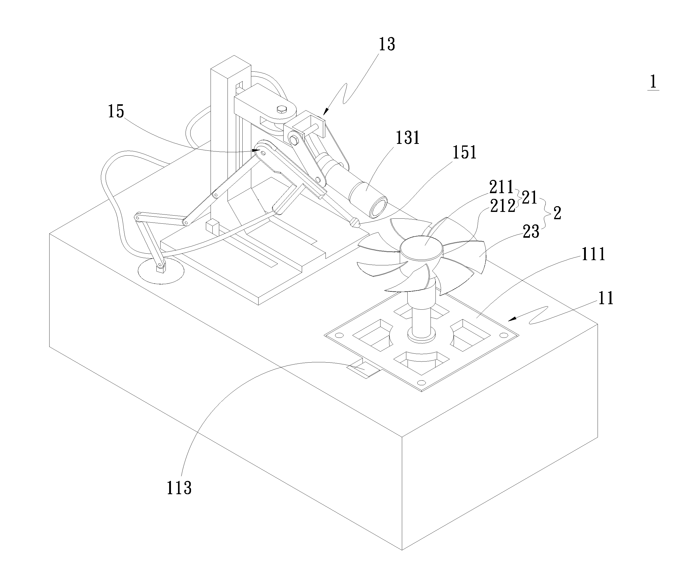
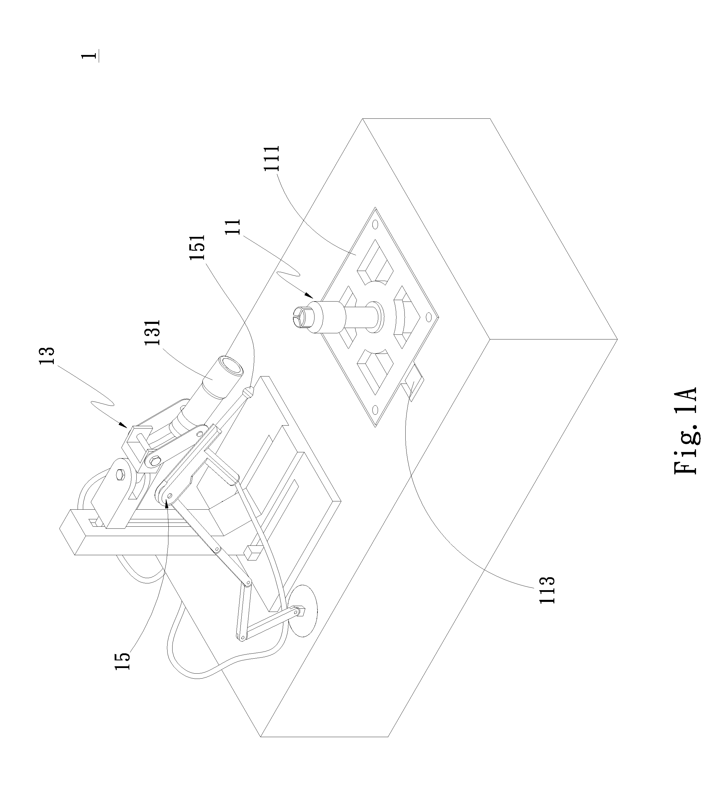
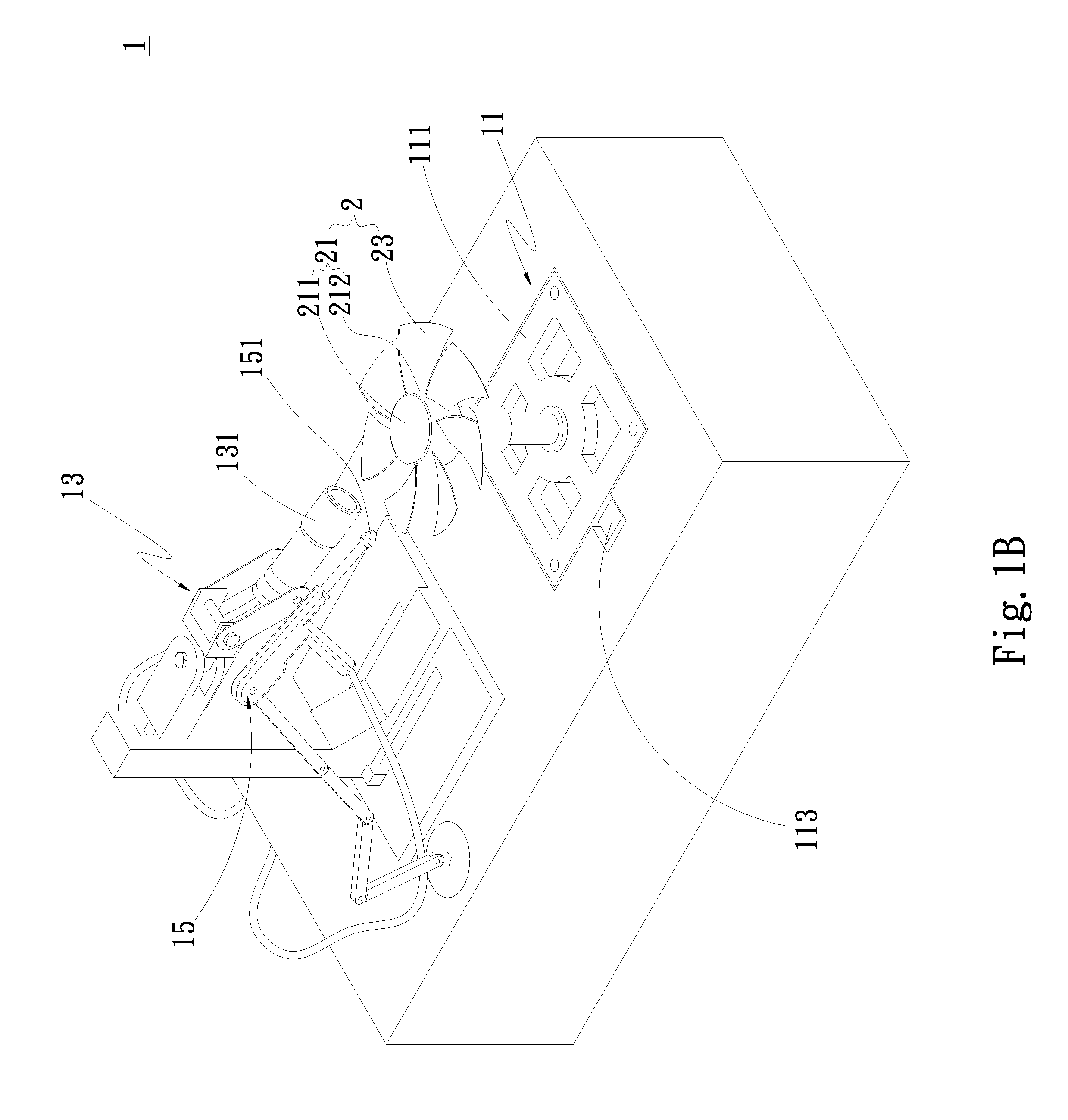
[0032]The present invention provides a rotor balance device for laser removal and a method thereof. Please refer to FIGS. 1A, 1B and 2 which are perspective views showing the first embodiment of the present invention respectively. The rotor balance device 1 includes a balance measurement unit 11, at least one laser unit 13, and an air-jetting unit 15. The balance measurement unit 11 is positioned opposite to the laser unit 13. The balance measurement unit 11 has a correcting platen 111 and at least one sensor 113. The correcting platen 111 is configured to support a rotor 2 to control the rotor 2 to rotate or not. The rotor 2 comprises a hub 21 and a plurality of blades 23 circumferentially provided on the hub 21. The hub 21 has a top portion 211 and a side portion 212 axially ext...
PUM
 Abstract
Description
Claims
Application Information