Cooking pan

Inactive Publication Date: 2013-12-19
PARK JONG PETER
View PDF6 Cites 6 Cited by
  • Summary
  • Abstract
  • Description
  • Claims
  • Application Information

AI Technical Summary

Benefits of technology

The present invention has the following advantages: (1.) It is easy to use in different types of ovens. (2.) It can be used for various purposes due to its flexible design and structure.

Problems solved by technology

Since it has to do so many things in the kitchen, a cooking pan cannot have enough of functions.

Method used


Image

  • Cooking pan
  • Cooking pan
  • Cooking pan

Examples


Embodiment Construction

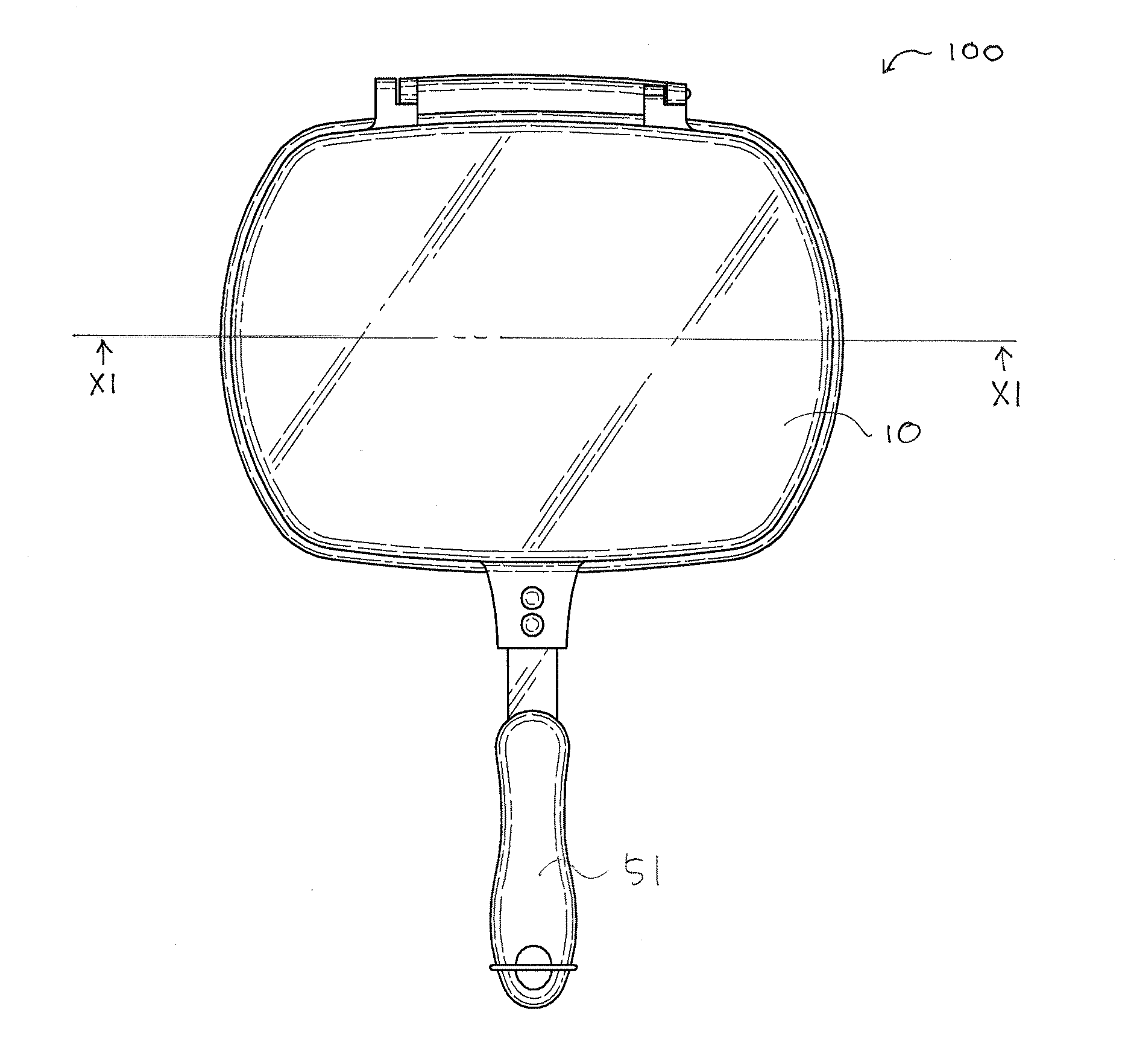
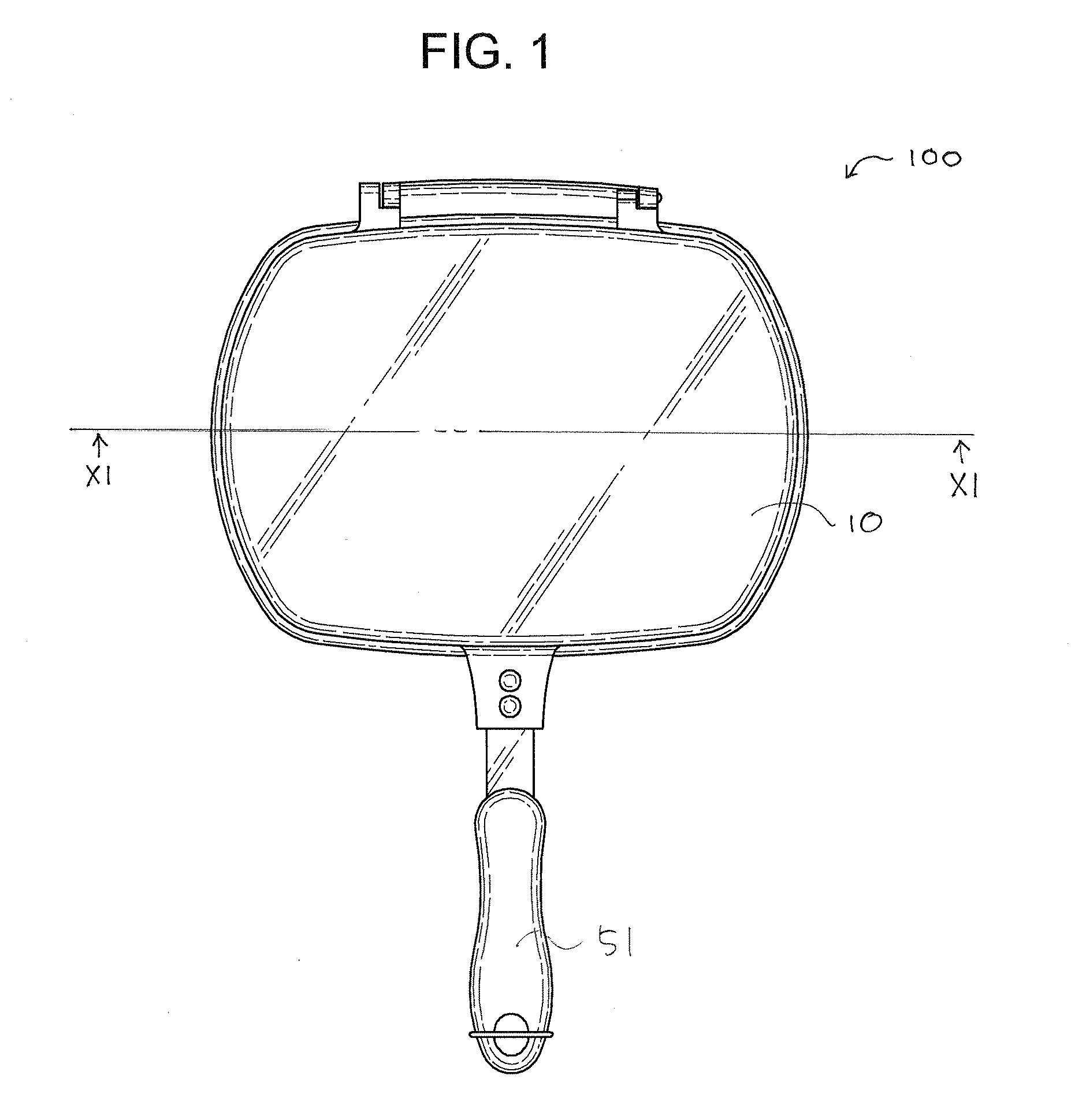
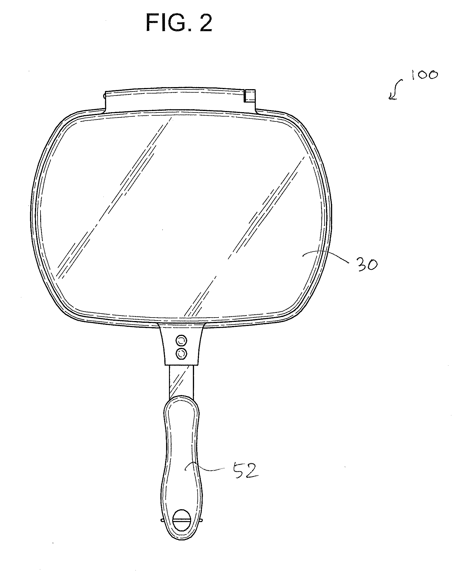
[0049]FIGS. 1-10 show cooking pans according to embodiments of the invention.

[0050]An object of the invention is to provide a cooking pan, more specifically a cooking pan which can be used on both of a gas oven and an induction oven.

[0051]An aspect of the invention provides a cooking pan 100, comprising a first pan portion 10, an induction heating layer 20, a second pan portion 30, and a non-induction heating layer 40 as shown in FIGS. 1-6.

[0052]The first pan portion 10 has a first bottom wall 12 and a first raised enclosing wall 14 as shown in FIG. 7.

[0053]The induction heating layer 20 is provided in the first bottom wall 12 as shown in FIG. 11.

[0054]The second pan portion 30 has a second bottom wall 32 and a second raised enclosing wall 34 as shown in FIG. 7.

[0055]The non-induction heating layer 40 is provided in the second bottom wall 32 as shown in FIG. 11.

[0056]The first pan portion 10 and the second pan portion 30 are symmetrically shaped with respect to bordering edge of the...


PUM


Abstract

A cooking pan includes a first pan portion, an induction heating layer, a second pan portion, and a non-induction heating layer. The first pan portion has a first bottom wall and a first raised enclosing wall. The induction heating layer is provided in the first bottom wall. The second pan portion has a second bottom wall and a second raised enclosing wall. The non-induction heating layer is provided in the second bottom wall. The first pan portion and the second pan portion are symmetrically shaped with respect to bordering edge of the raised enclosing walls.

Description

BACKGROUND OF THE INVENTION[0001]The present invention relates to a cooking pan.[0002]Kitchen is a place at the center of the house in a sense, and cooking is an art for living.[0003]Since it has to do so many things in the kitchen, a cooking pan cannot have enough of functions. If it has one more function, the cooking pan may be a bless sometimes.[0004]Accordingly, a need for a cooking pan has been present for a long time considering the expansive demands in the everyday life. This invention is directed to solve these problems and satisfy the long-felt need.SUMMARY OF THE INVENTION[0005]The present invention contrives to solve the disadvantages of the prior art.[0006]An object of the invention is to provide a cooking pan, more specifically a cooking pan which can be used on a gas oven and an induction oven.[0007]A cooking pan includes a first pan portion, an induction heating layer, a second pan portion, and a non-induction heating layer.[0008]The first pan portion has a first bott...

Claims


Application Information

Patent Timeline
IPC IPC(8): H05B6/12
CPCA47J27/002H05B6/1209A47J37/10
Inventor PARK, JONG PETER
Owner PARK JONG PETER
Why Eureka
Try Eureka