
Electric vehicle charge scheduling method and charge scheduling device

a technology for charging scheduling and electric vehicles, applied in charging stations, transportation and packaging, instruments, etc., can solve problems such as battery shortage condition, inability to provide information, so as to improve the convenience of users and improve the readiness and operation reliability of the system.

Inactive Publication Date: 2013-12-19
AISIN SEIKI KK
View PDF5 Cites 74 Cited by
  • Summary
  • Abstract
  • Description
  • Claims
  • Application Information

AI Technical Summary

Benefits of technology

The present invention is a battery charge scheduling method and device for electric vehicles. The purpose is to improve user convenience by allowing battery charge reservations based on user preferences and risks. This also helps to relieve anxiety and risks associated with low battery charge. Additionally, the system works better and is more reliable because it reduces the processing load on the vehicle's side.

Problems solved by technology

However, according to this method, another issue arises that if the number of secondary battery supply systems is only one existed in a certain area, the information on all electric vehicles needed to supply battery come to this system at one time, and the information processing in the system may delay or the system itself may be broken due to an excess load.
This may stop information providing services.
If a plurality of such secondary battery supply systems exists in a certain area, it is necessary to individually make access to each system from each electric vehicle, which may be troublesome.
This may also be troublesome.
For example, if the vehicle is running using the air-conditioner, the in-vehicle battery is rapidly consumed and may become battery shortage condition even before the vehicle reaches within the available mileage distance calculated by the server based on the average mileage distance data base.

Method used


Image

  • Electric vehicle charge scheduling method and charge scheduling device
  • Electric vehicle charge scheduling method and charge scheduling device
  • Electric vehicle charge scheduling method and charge scheduling device

Examples


Embodiment Construction

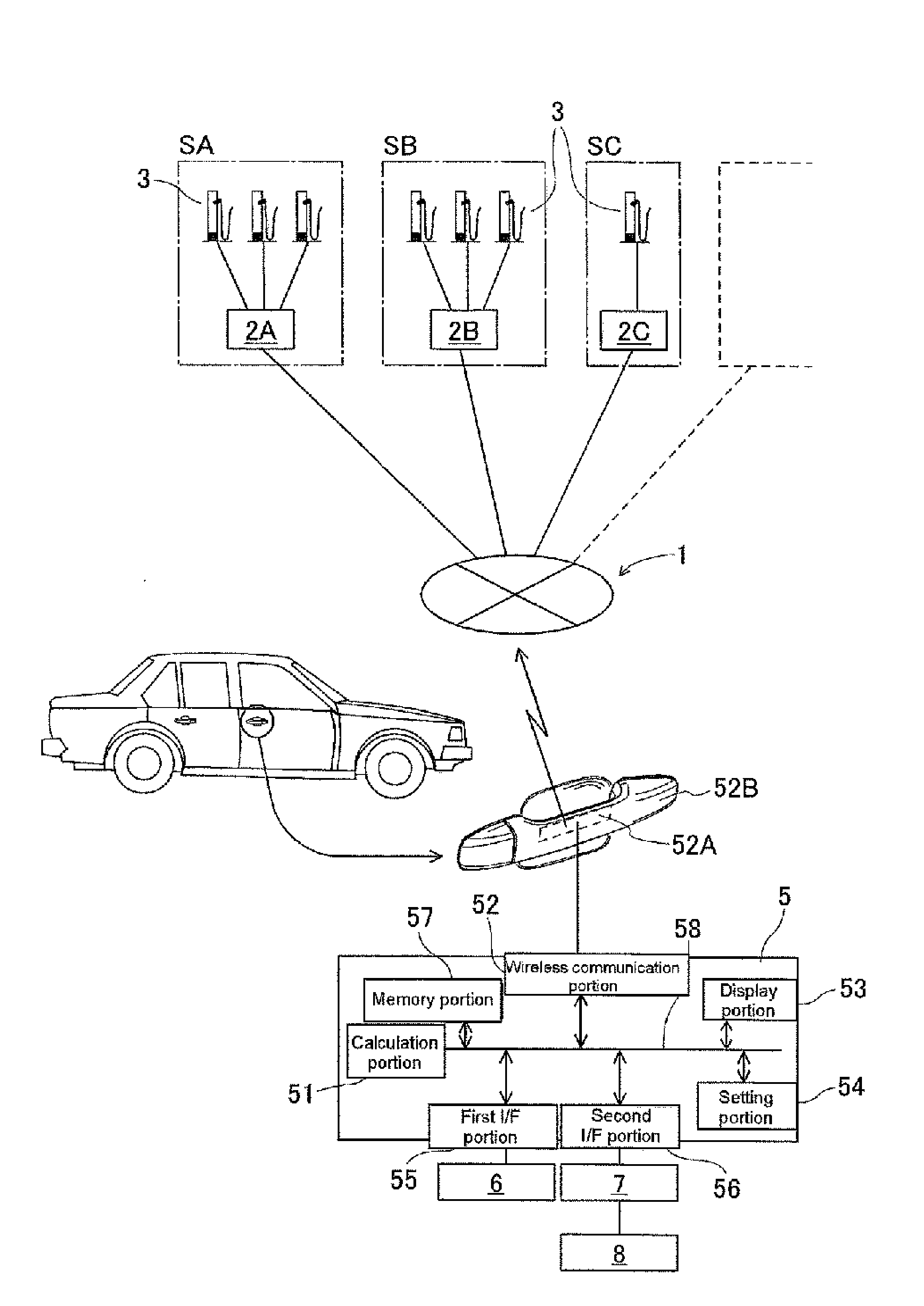
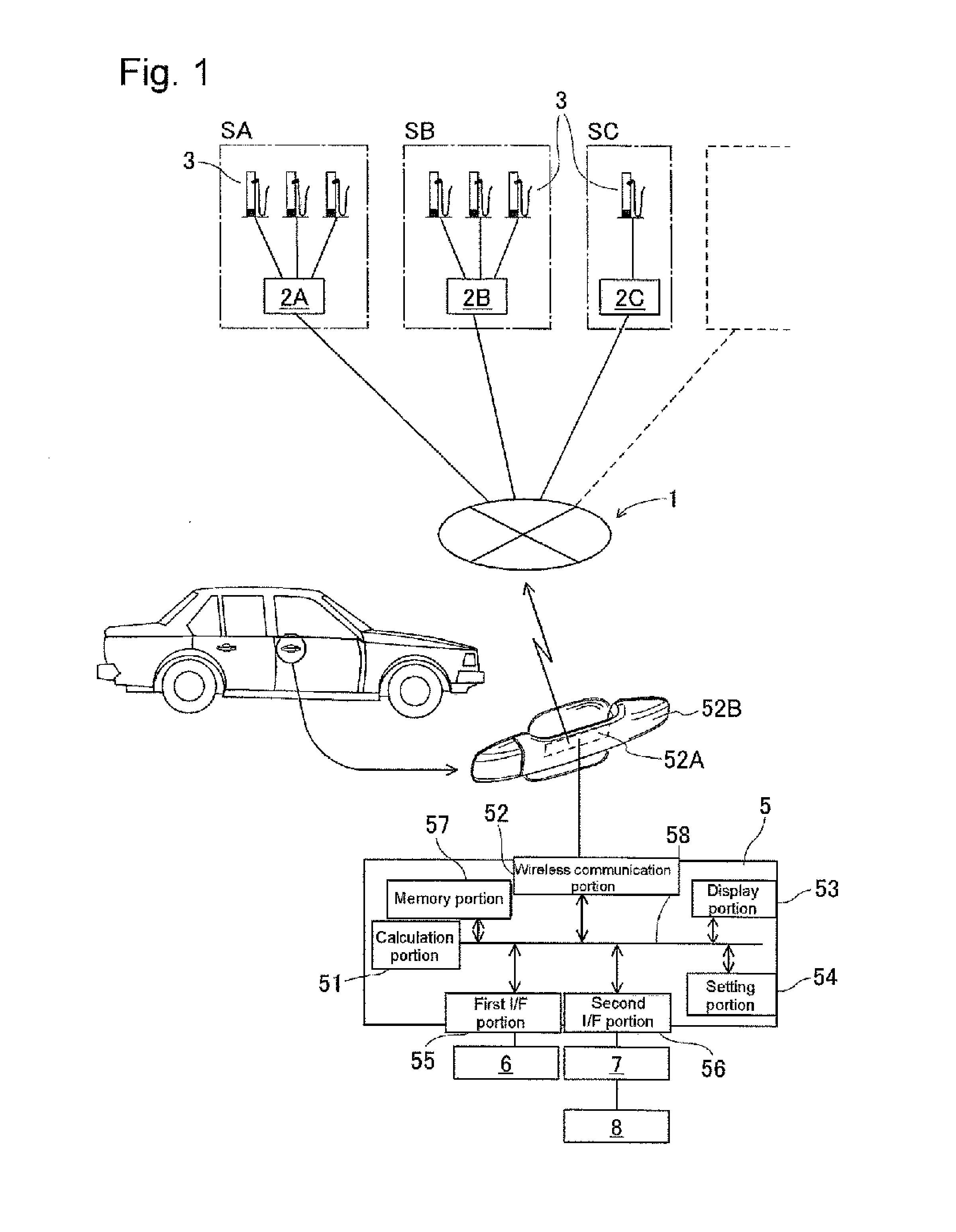
[0018]An embodiment of the method for battery charge scheduling for an electric vehicle according to the invention will be explained with reference to the attached drawings, FIGS. 1 through 3. FIG. 1 is a schematically illustrated station control network and the in-vehicle information device to be used for the method for battery charge scheduling for an electric vehicle. As shown in the drawing, the station control network 1 is formed by a plurality of station control devices 2A, 2B and 2C which are mutually cooperative to exchange information therebetween. The in-vehicle information device 5 is installed in an electric vehicle and the information thereof is exchangeable with the information of the station control network 1 through a wireless communication. This structure will be explained in detail hereinafter.

[0019]The station control devices 2A, 2B and 2C are provided in respective battery charge stations SA, SB and SC and each device 2A, 2B and 2C controls one or a plurality of ...


PUM


Abstract

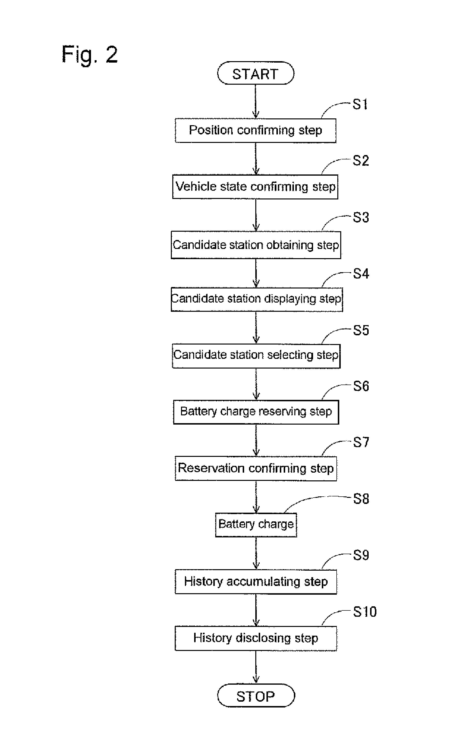
A method for battery charge scheduling for an electric vehicle including a position confirming step for confirming a position of the vehicle, a candidate station obtaining step for obtaining information on position of the candidate battery charge station, a waiting time and a battery charge cost, a candidate battery charge station displaying step for displaying the information of the candidate battery charge stations, a candidate battery charge station selecting step for selecting a candidate battery charge station at which a battery charge is desired to be carried out and a battery charge reserving step for reserving the battery charge at the candidate battery charge station through the station control network based on a setting at the candidate battery charge station selecting step through the in-vehicle information device. By this method, user convenience is improved and actual risks and mental anxieties derived from low battery charge can be relieved or removed.

Description

TECHNICAL FIELD[0001]This invention relates to a method for and a device of scheduling battery charge timing for an electric automobile or an electric vehicle at a battery charge station equipped with a battery charge facility.BACKGROUND OF THE TECHNOLOGY[0002]Recently, an electric vehicle has been gradually becoming popularized and the battery charge equipment for charging battery of such electric automobiles has been now gradually developed and maintenance of charge stations for public use is being in progress. However, at present, the mileage of the electric automobile or vehicle is not so good compared to that of other vehicles, such as a gas driven car, a diesel driven car or a liquefied natural gas (LNG) driven car and further the number of the equipment of the battery charge for the electric vehicle is less than the number of the gas station for the other vehicles. Due to such situations, when one drives away with an electric vehicle, it is necessary for the operator of the v...

Claims


Application Information

Patent Timeline
Patent Type & Authority Applications(United States)
IPC IPC(8): G06Q10/02G06Q50/30B60L11/18
CPCG06Q10/02B60L11/1838G06Q50/30G06Q10/00B60L53/66Y02T90/16Y02T10/70Y02T90/12Y02T10/7072G06Q50/40
Inventor TOUGE, HIROSHI
Owner AISIN SEIKI KK
Learn More