Display panel

Active Publication Date: 2013-12-26
IND TECH RES INST
View PDF26 Cites 18 Cited by
  • Summary
  • Abstract
  • Description
  • Claims
  • Application Information

AI Technical Summary

Benefits of technology

The patent describes a display panel that has good deep color display. The panel has a low ratio of light-emitting device to pixel region, which increases its transparency. Additionally, solar cells are placed in the panel, which can control the display's grayscale to achieve better deep color display.

Problems solved by technology

However, the current transparent display faces problems such as not having enough transparency and difficulty in displaying deep color.
If the transparency of the display is low, the user will clearly perceive the presence of the display and not be able to clearly observe the background behind the display.
Therefore, the transparent display has the prevalent problem of poor deep color display due to difficulty in grayscale control.

Method used


Image

  • Display panel
  • Display panel
  • Display panel

Examples


second embodiment

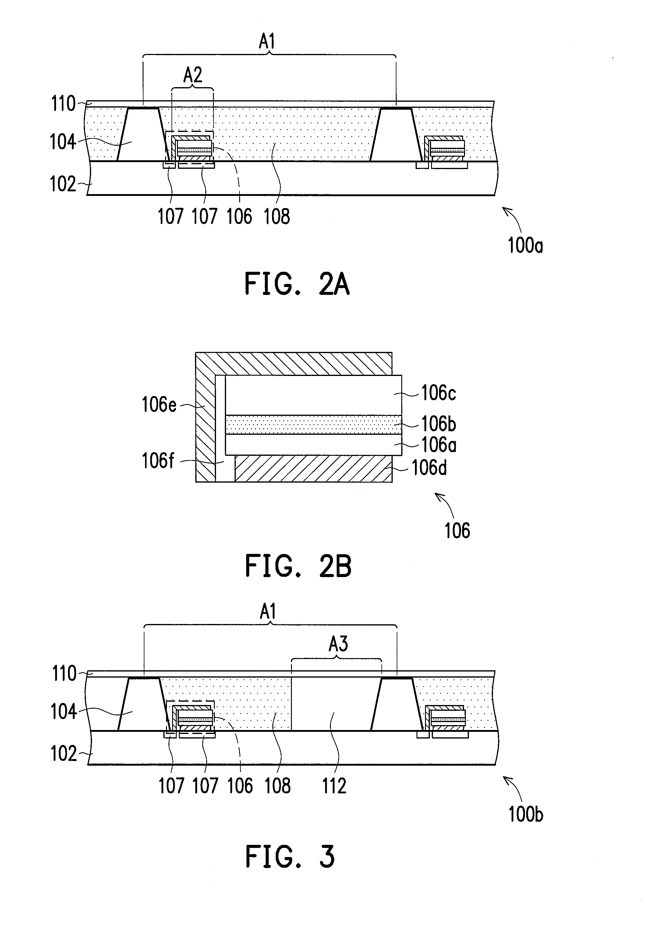
[0034]Other embodiments are listed below for explanation, wherein the same reference numerals represent the same or similar components. Moreover, the top schematic views of the following number of embodiments are as shown in FIG. 1. FIG. 3 is a schematic cross-sectional view of a portion of a display panel of the disclosure. Referring to FIG. 1 and FIG. 3, the display panel 100b is substantially similar to the display panel 100a of FIG. 2A, wherein the difference between the two is that the display panel 100b further includes an optical adhesive 112. The optical adhesive 112 is, for instance, transparent colloids having a certain degree of light transmittance, and may have the same material as the transparent colloids used in the diffusion adhesive 108, wherein since the diffusion adhesive 108 further includes a plurality of diffusion particles, the light transmittance of the optical adhesive 112 is higher than the overall light transmittance of the diffusion adhesive 108. Of course...

third embodiment

[0036]FIG. 4 is a schematic cross-sectional view of a portion of a display panel of the disclosure. Referring to FIG. 1 and FIG. 4, the display panel 100c is substantially similar to the display panel 100a of FIG. 2A, wherein the difference between the two is that the light-emitting devices 106 of the display panel 100c are partially disposed in the meshed shielding pattern 104. In other words, the light-emitting devices 106 are partially embedded in the meshed shielding pattern 104. The meshed shielding pattern 104 covers the light-emitting devices 106 and exposes a side 106s of the light-emitting devices 106. In the present embodiment, the light-emitting devices 106 provide a light source by emitting light from the side. Specifically, when the meshed shielding pattern 104 covers the light-emitting devices 106 such that the light-emitting devices 106 emit light from the side 106s, a reflective material may further be disposed in the light-emitting devices 106, and the reflective ma...

fourth embodiment

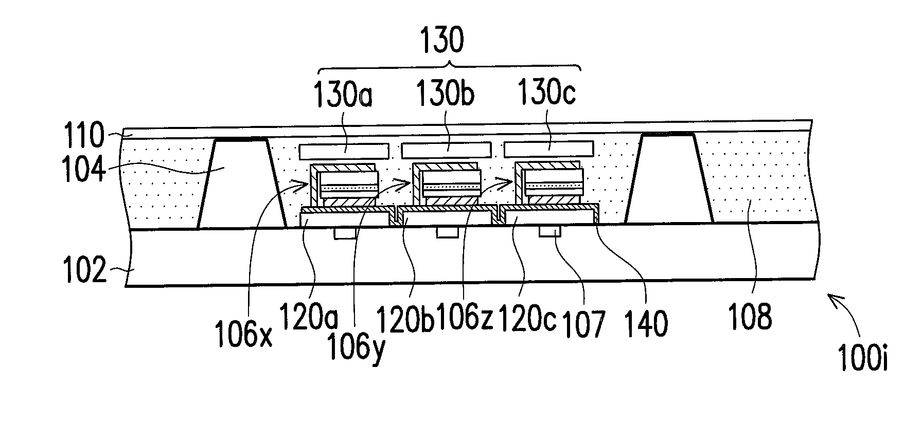
[0038]FIG. 5 is a schematic cross-sectional view of a portion of a display panel of the disclosure. Referring to FIG. 1 and FIG. 5, the display panel 100d is substantially similar to the display panel 100a of FIG. 2A, wherein the difference between the two is that three light-emitting devices are disposed in the pixel regions U of the display panel 100d. Specifically, light-emitting devices 106x, 106y, and 106z are stacked upon one another and each light-emitting device is at least partially exposed. For instance, since the light-emitting device 106y is stacked upon the light-emitting device 106z, the light-emitting device 106z is only partially exposed. Similarly, since the light-emitting device 106x is stacked upon the light-emitting device 106y, the light-emitting device 106y is only partially exposed. Moreover, the light-emitting device 106x is completely exposed. In the present embodiment, the light-emitting devices 106x, 106y, and 106z are respectively a red light-emitting dev...


PUM


Abstract

A display panel including a substrate, a meshed shielding pattern, and a plurality of light-emitting devices is provided. The meshed shielding pattern is disposed on the substrate so as to define a plurality of pixel regions on the substrate. The light-emitting devices are disposed on the substrate. At least one light-emitting device of the light-emitting devices is disposed in each pixel region of the pixel regions, wherein an area of the pixel region is A1, an area of the light-emitting device is A2, and a ratio of A2 to A1 is below 50%.

Description

CROSS-REFERENCE TO RELATED APPLICATION[0001]This application claims the priority benefits of U.S. provisional application Ser. No. 61 / 662,931, filed on Jun. 22, 2012 and Taiwan application serial no. 102119355, filed on May 31, 2013. The entirety of each of the above-mentioned patent applications is hereby incorporated by reference herein and made a part of this specification.TECHNICAL FIELD[0002]The disclosure relates to a transparent display panel.BACKGROUND[0003]The transparent display is a display having a certain degree of inherent transparency, wherein in addition to displaying information or pictures, the transparent display further allows the user to clearly see the background behind the display. Currently, the transparent display is suitable for various applications in, for instance, windows of buildings, car windows, and shopwindows, and has therefore garnered market attention.[0004]However, the current transparent display faces problems such as not having enough transpare...

Claims


Application Information

Patent Timeline
IPC IPC(8): H01L27/15
CPCH01L27/156G02F1/157G02F2201/44G02F1/13324H01L25/0753H01L25/0756H10K59/32H10K59/35H10K59/38H10K59/50H10K59/173H10K2102/3031H10K59/873H10K59/00H10K50/865
Inventor LIN, JUI-YINGCHAO, CHIA-HSINTAI, KUANG-YUYEH, WEN-YUNG
Owner IND TECH RES INST
Why Eureka
Try Eureka