Tweezer Device Incorporating Improved Gripping Tip Structures, and Method of using

Active Publication Date: 2013-12-26
STAYTON STEPHEN BURTON
View PDF12 Cites 9 Cited by
  • Summary
  • Abstract
  • Description
  • Claims
  • Application Information

AI Technical Summary

Problems solved by technology

These common tweezer tip configurations are suitable to grip a wide variety of work object shapes but in many cases the work object is not well constrained by the simple tweezer tip configuration and

Method used


Image

  • Tweezer Device Incorporating Improved Gripping Tip Structures, and Method of using
  • Tweezer Device Incorporating Improved Gripping Tip Structures, and Method of using
  • Tweezer Device Incorporating Improved Gripping Tip Structures, and Method of using

Examples


first embodiment

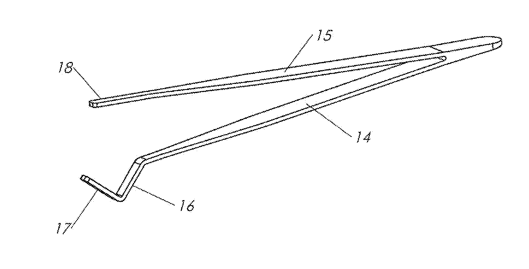
[0012]tweezer according to the present invention is shown in FIG. 6. A first flexible beam 14 and a second flexible beam 15 support the tweezer gripping tips in a conventional manner. The two vee configured tip bodies 16 and 17 are located at the distal end of first beam 14 as shown. A single opposing gripping tip 18 is located at the distal end of second beam 15. In this embodiment, each of the three gripping tip bodies incorporates a flat surface for the gripping face that engages in contact with the work object. In this embodiment the included angle between the two vee tip gripping faces is 90 degrees.

[0013]FIGS. 7 and 8 show a cylinder shaped work object gripped by the tweezer tip configuration of the first embodiment, in accordance with the tweezer device and method of the present invention. By nature of the well understood kinematic characteristics of a vee support structure with two flat functional faces, a cylindrical shaped solid object of any size, within the maximum or mi...

second embodiment

[0020]FIG. 22 shows the tweezer device of the present invention where the vee configured gripping tips have variable radius, non-flat gripping surfaces but maintain the symmetrical geometry of a functional kinematic vee support structure. A convex involute profile is shown in this example but other variable radius shapes are effective as long as the symmetrical vee geometry maintains the function of a kinematic vee support structure for the two gripping tips on the distal end of the first tweezer beam and are opposed by a third gripping tip on the distal end of the second tweezer beam. The convex involute vee configuration provides for an increase in the maximum diameter capacity of the vee structure for cylinder type objects.

third embodiment

[0021]FIG. 23 shows the tweezer device of the present invention that incorporates a variation in the orientation of the third gripping tip body relative to the second flexible tweezer beam that allows for very small dimensioned objects to be securely gripped in the two opposing vee configured tip bodies while still allowing larger objects to be securely gripped. FIGS. 24 and 25 show this embodiment of the invention gripping a relative small diameter cylinder and FIG. 26 shows it gripping a relative large sized cylinder.

[0022]FIGS. 27A-D show a fourth embodiment of a tweezer tip configuration for a tweezer device and method according to the present invention that incorporates an additional feature into the tip configuration of the first embodiment. A longitudinal groove, with an elective vee cross sectional shape, is centrally located on each of the three tweezer tip gripping faces. This additional groove feature is configured to allow the secure gripping of thin disk, or coin shaped...


PUM


Abstract

A tweezer device and method of using that provides an improved gripping tip concept for gripping a work object. The tweezer device comprises two gripping tip bodies arranged in a symmetric vee configuration supported on a first flexible tweezer beam, and a third gripping tip body supported on a second flexible tweezer beam arranged in such a manner that the third gripping tip body engages a work object and directs a force on the work object that is approximately coplanar with the plane of symmetry of the vee configured structure in a manner that pushes the work object into contact with the two vee configured gripping tip bodies thus forming two lines of contact between the work object and the vee configured tip bodies.

Description

RELATED APPLICATION / CLAIM OF PRIORITY[0001]This application is related to and claims priority from U.S. provisional application Ser. No. 61 / 663,592, filed Jun. 24, 2012, and entitled Tweezer Device Incorporating Improved Gripping Tip Structures, which provisional application is incorporated by reference herein.INTRODUCTION[0002]The current invention relates to the design of the gripping tips of tweezer devices, and to a method of using the tweezer with those gripping tip structures.[0003]The most common configuration of tweezers comprises two flexible beams joined together at a proximal end and two opposing gripping tips each of which is located at the distal end of each beam. The gripping tips are the functional ends of the tweezer beams typically used to grip an object, the work object, for manipulation by the tweezer operator. To grip the work object the operator applies finger pressure on each tweezer beam to deflect the beams in a manner that moves the gripping tips closer toge...

Claims


Application Information

Patent Timeline
IPC IPC(8): B25B9/02
CPCB25B9/02
Inventor STAYTON, STEPHEN BURTON
Owner STAYTON STEPHEN BURTON
Why Eureka
Try Eureka