
Snap-in insert for reactivity control in spent nuclear fuel pools and casks

a nuclear fuel pool and insert technology, applied in nuclear engineering, nuclear elements, greenhouse gas reduction, etc., can solve the problems of less than optimal neutron absorbing assemblies, generally devoid of traditional layers and the deterioration of neutron absorbing materials

Inactive Publication Date: 2013-12-26
HOLTEC INT
View PDF3 Cites 12 Cited by
  • Summary
  • Abstract
  • Description
  • Claims
  • Application Information

AI Technical Summary

Benefits of technology

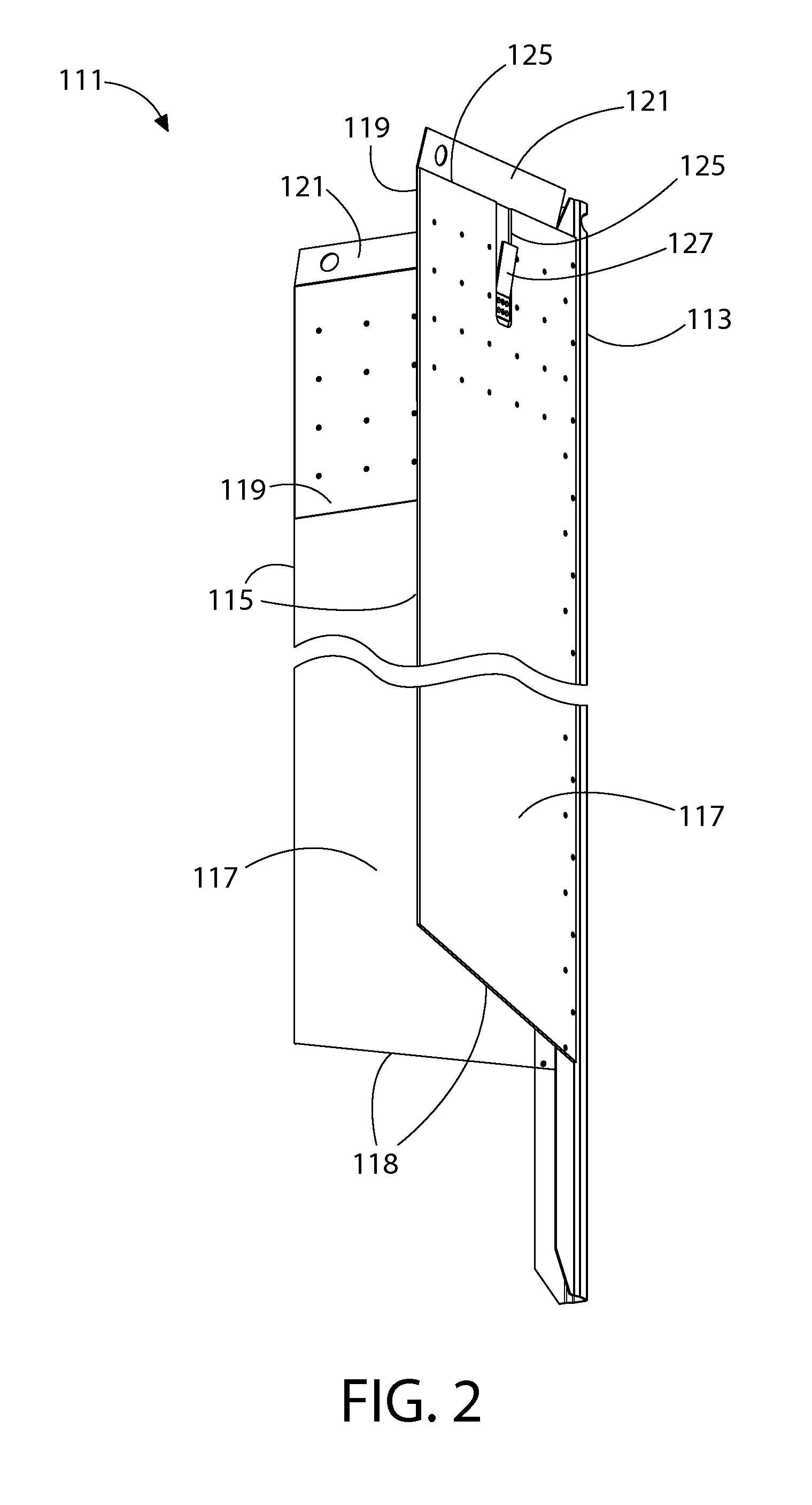
The present invention is about a neutron absorbing apparatus that can be used in spent fuel cell transport and storage systems. The apparatus includes a corner spine and first and second walls, each affixed to the corner spine to form a chevron shape. The absorption sheet is made of a metal matrix composite with neutron absorbing particulate reinforcement and is affixed to the corner spine. The guide sheet covers an upper portion of the absorption sheet and also extends over a top of it. The apparatus can be retrofitted into existing fuel cell storage systems by inserting it into one cell and creating locking protuberances to secure it in place. The technical effects of this invention include improved safety and protection against the risk of radiation exposure during the handling and transport of spent nuclear fuel.

Problems solved by technology

However, these neutron absorbing materials have begun to deteriorate as they have been submerged in water for over a decade.
Thus, newer fuel racks are generally devoid of the traditional layer of neutron absorbing material built into the structure of the fuel rack itself that can degrade over time.
While the neutron absorbing assemblies disclosed in the prior art have proved to be preferable to the old fuel racks having the neutron absorbing material integrated into the cell walls, these neutron absorbing assemblies are less than optimal for a number of reasons, including without limitation complexity of construction, the presence of multiple welds, complicated securing mechanisms, and multi-layered walls that take up excessive space within the fuel rack cells.
This not only complicates the handling procedure but also leaves certain cells in a potentially unprotected state.

Method used

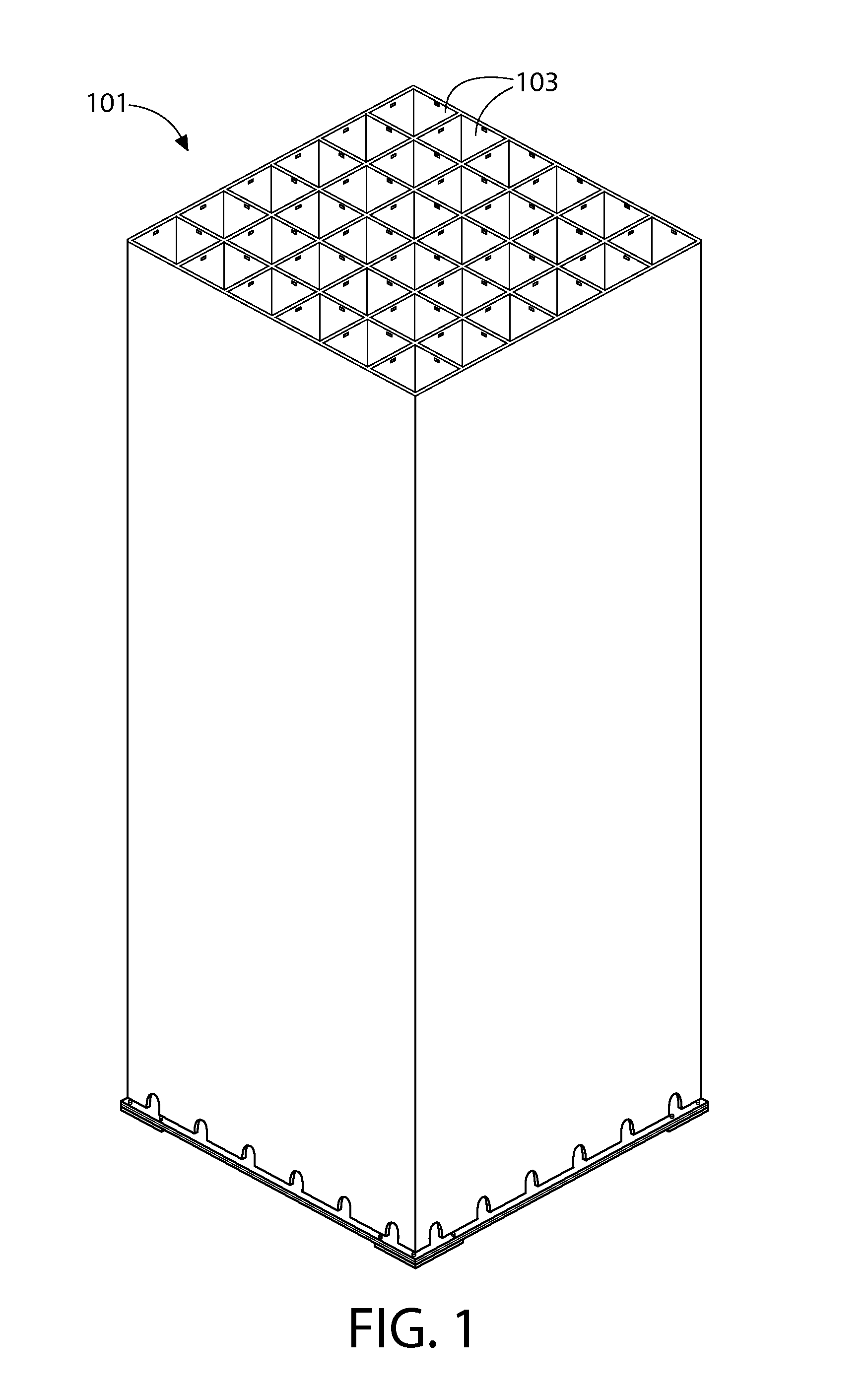

Image

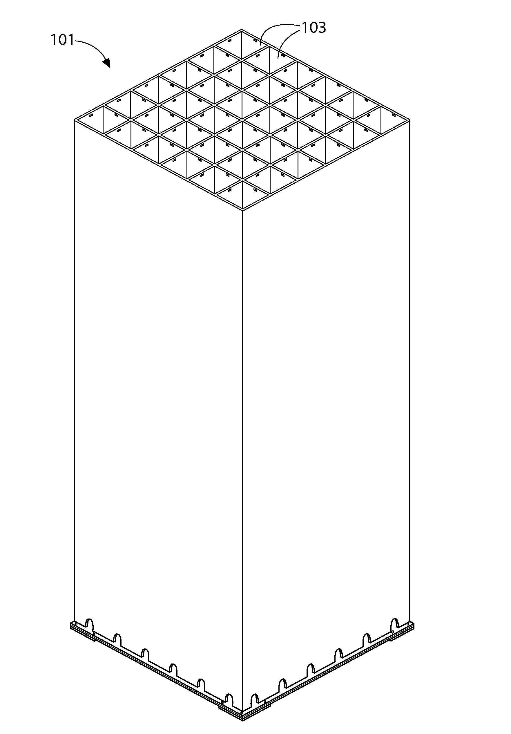
  • Snap-in insert for reactivity control in spent nuclear fuel pools and casks
  • Snap-in insert for reactivity control in spent nuclear fuel pools and casks
  • Snap-in insert for reactivity control in spent nuclear fuel pools and casks

Examples


Embodiment Construction

[0024]The description of illustrative embodiments according, to principles of the present invention is intended to be read in connection with the accompanying drawings, which are to be considered part of the entire written description, in the description of embodiments of the invention disclosed herein, any reference to direction or orientation is merely intended for convenience of description and is not intended in any way to limit the scope of the present invention. Relative terms such as “lower,”“upper,”“horizontal,”“vertical,”“above,”“below,”“up,”“down,”“left,”“right,”“top” and “bottom” as well as derivatives thereof (e.g., “horizontally,”“downwardly,”“upwardly,” etc.) should be construed to refer to the orientation as then described or as shown in the drawing under discussion. These relative terms are for convenience of description only and do not require that the apparatus be constructed or operated in a particular orientation unless explicitly indicated as such. Terms such as...


PUM


Abstract

A neutron absorbing apparatus, for insertion into a fuel cell storage system, includes a corner spine, a first all and a second wall, each wall being affixed to the corner spine to form a chevron shape. Each wall includes an absorption sheet affixed to the corner spine, each absorption sheet being formed of a metal matrix composite having neutron absorbing particulate reinforcement, and a guide sheet affixed to and covering a fractional upper portion of the absorption sheet and extending over a top of the absorption sheet. The absorption sheet extends along the corner spine a greater length than the guide sheet.

Description

CROSS REFERENCE TO RELATED APPLICATIONS[0001]Priority is claimed to U.S. provisional patent application No. 61 / 663,316, filed Jun. 22, 2012, the disclosure of which is incorporated herein by reference in its entirety.FIELD OF THE INVENTION[0002]The field of the present invention relates to neutron absorbing apparatus and methods used to facilitate close packing, of spent nuclear fuel assemblies.BACKGROUND OF THE INVENTION[0003]Nuclear power plants currently store their spent fuel assemblies on site for a period after being removed from the reactor core. Such storage is typically accomplished by placing the spent fuel assemblies in closely packed fuel racks located at the bottom of on-site storage pools. The storage pools provide both radiation shielding and much needed cooling for the spent fuel assemblies.[0004]Fuel racks often contain a large number of closely arranged adjacent storage cells wherein each cell is capable of accepting a spent fuel assembly. In order to avoid critica...

Claims


Application Information

Patent Timeline
IPC IPC(8): G21F5/012
CPCG21C19/07G21C19/40G21F5/012G21F1/08G21F1/06Y02E30/30
Inventor AGACE, STEPHEN J.THOMPSON, STEPHEN E.GRIFFITHS, JOHN D.SPRINGMAN, RICHARD M.
Owner HOLTEC INT
Learn More