Industrial Hardware Installation Base Reporting And Failure Monitoring

a technology for industrial hardware and installation base, applied in the field of industrial control system, can solve the problems of costly downtime and/or product defects, manual data collection is often time-consuming and subject to human error, and industrial system may typically chang

Active Publication Date: 2013-12-26
ROCKWELL AUTOMATION TECH
View PDF5 Cites 25 Cited by
  • Summary
  • Abstract
  • Description
  • Claims
  • Application Information

AI Technical Summary

Benefits of technology

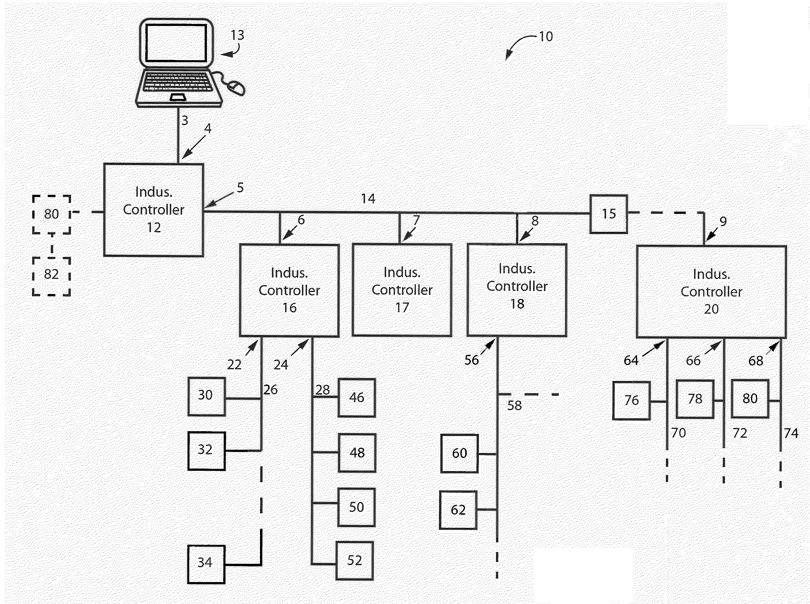
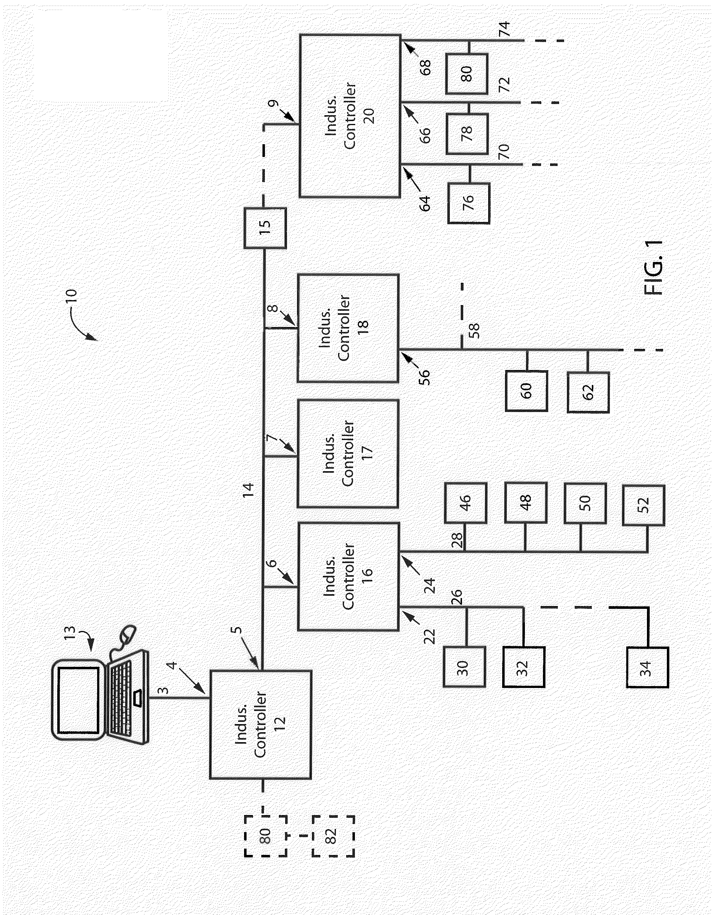
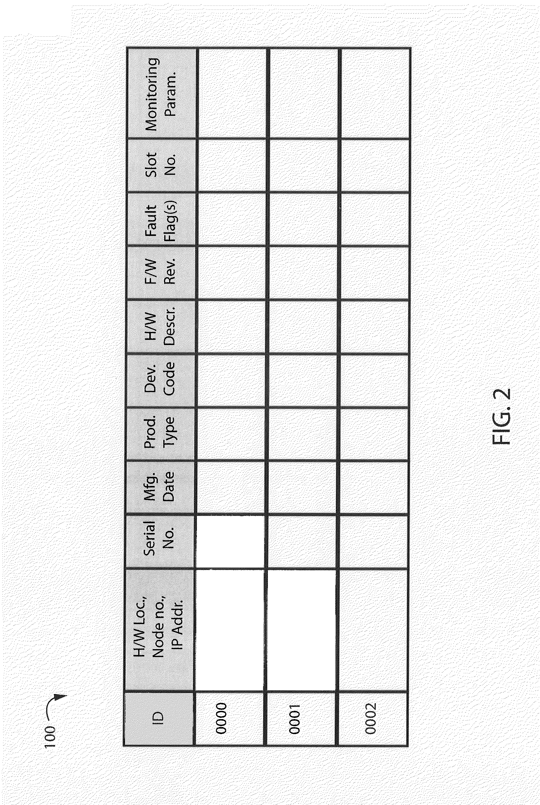
[0008]Aspects of the present invention provide an industrial controller with a processor executing a program stored in a non-transitory computer-readable storage medium and having a user interface and a network interface. The network interface allows communicating over a first control network with another industrial controller having a network interface. The other industrial controller also has an additional network interface for communicating over a second control network with an industrial device. The program instructs the processor to perform the following steps: (a) retrieve installation information contained in the other industrial controller and the industrial device by communicating over the first control network and over the second control network; (b) build a data str

Problems solved by technology

This may occur, for example, when interrupting the process would cause costly downtime and/or product defects.
Consequently, the industrial system may typically change over time and throughout physically dispersed areas in the factory.
However, collection of additional installation information at the primary level, such as the hardware area location with node number or IP address, product type, device code, hardware description, firmware revision, major and minor fault flag, slot number, and important condition monitoring parameters, and collection of any information contained in no

Method used


Image

  • Industrial Hardware Installation Base Reporting And Failure Monitoring
  • Industrial Hardware Installation Base Reporting And Failure Monitoring
  • Industrial Hardware Installation Base Reporting And Failure Monitoring

Examples


Embodiment Construction

[0024]One or more specific embodiments of the present invention will be described below. It is specifically intended that the present invention not be limited to the embodiments and illustrations contained herein, but include modified forms of those embodiments including portions of the embodiments and combinations of elements of different embodiments as come within the scope of the following claims. It should be appreciated that in the development of any such actual implementation, as in any engineering or design project, numerous implementation-specific decisions must be made to achieve the developers' specific goals, such as compliance with system-related and business related constraints, which may vary from one implementation to another. Moreover, it should be appreciated that such a development effort might be complex and time consuming, but would nevertheless be a routine undertaking of design, fabrication, and manufacture for those of ordinary skill having the benefit of this...


PUM


Abstract

An industrial control system includes an industrial controller with a processor executing a program stored in a non-transitory computer-readable storage medium and having a user interface and a network interface for communicating over a first control network with another industrial controller having a network interface. The other industrial controller has an additional network interface for communicating over a second control network with an industrial device. The program instructs the processor to retrieve installation information contained in the other industrial controller and the industrial device; build a data structure comprising the retrieved information; periodically monitor for a hardware failure; and send a message alarm in response to detection of a hardware failure. As a result, the installation base of the industrial system and any hardware failures are quickly understood and martial data collection is avoided.

Description

BACKGROUND OF THE INVENTION[0001]The present invention relates to industrial control systems and, in particular, to the retrieval of installation information and monitor of hardware failures in industrial control systems.[0002]Industrial controllers, such as programmable logic controllers (PLC's), are specialized electronic computer systems used for the control of industrial processes or machinery, for example, in a factory environment. Industrial controllers differ from conventional computers in a number of ways. Physically, they are constructed to be substantially more robust against shock and damage and to better resist external contaminants and extreme environmental conditions. The processors and operating systems are optimized for real-time control and execute languages allowing ready customization of programs to comport with a variety of different controller applications. Industrial controllers may have a user interface for accessing, controlling and / or monitoring the industri...

Claims


Application Information

Patent Timeline
IPC IPC(8): G05B15/00
CPCG05B19/0428
Inventor GARG, ANIKA
Owner ROCKWELL AUTOMATION TECH
Why Eureka
Try Eureka