Microphone mounting device and open-face helmet
a microphone and mounting device technology, applied in the direction of headwear caps, protective garments, hats, etc., can solve the problem that the microphone may not take voice input properly
- Summary
- Abstract
- Description
- Claims
- Application Information
AI Technical Summary
Benefits of technology
Problems solved by technology
Method used
Image
Examples
first embodiment
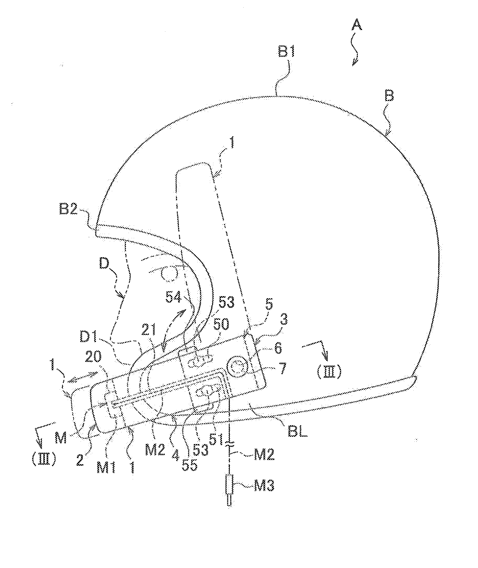
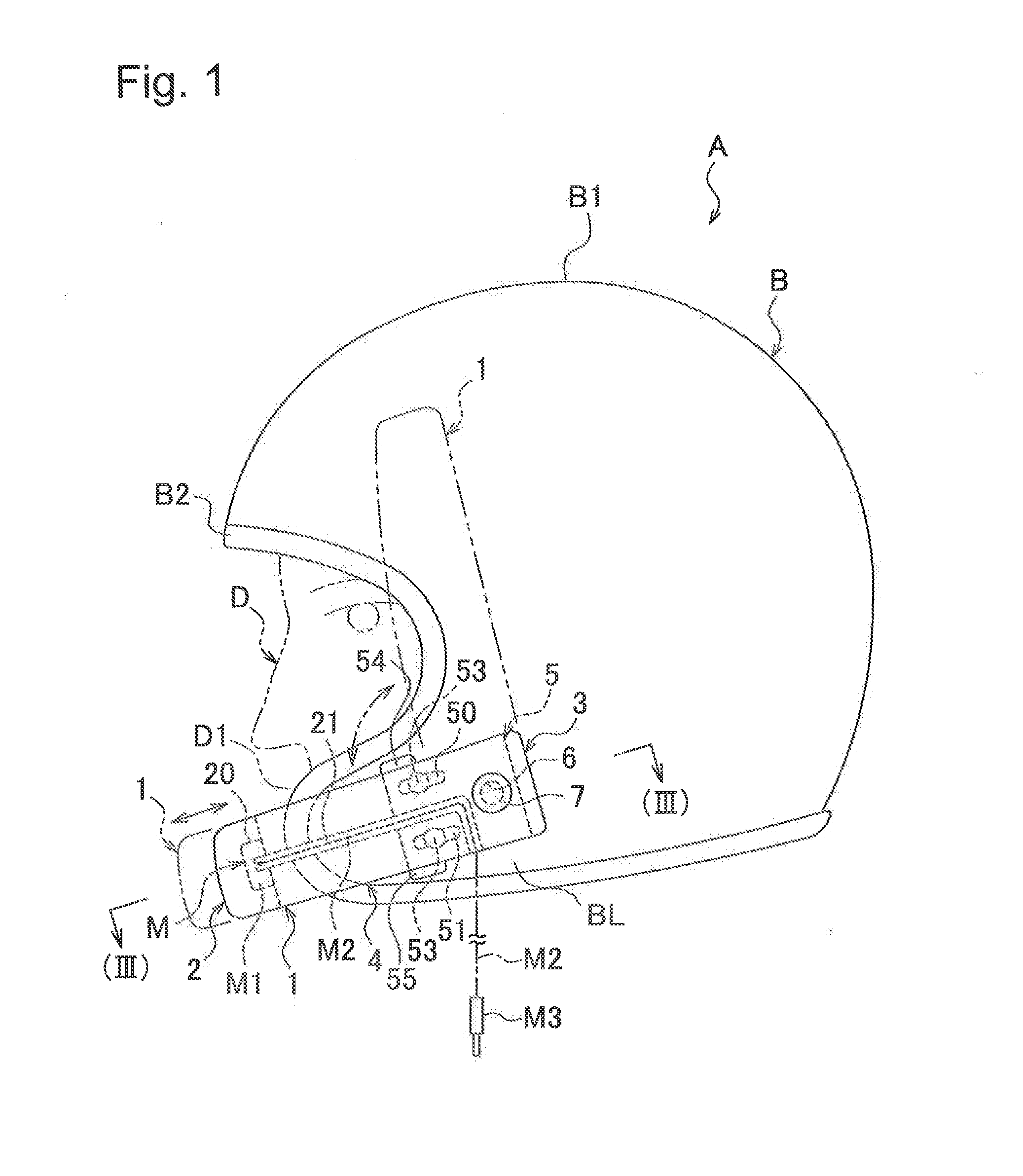
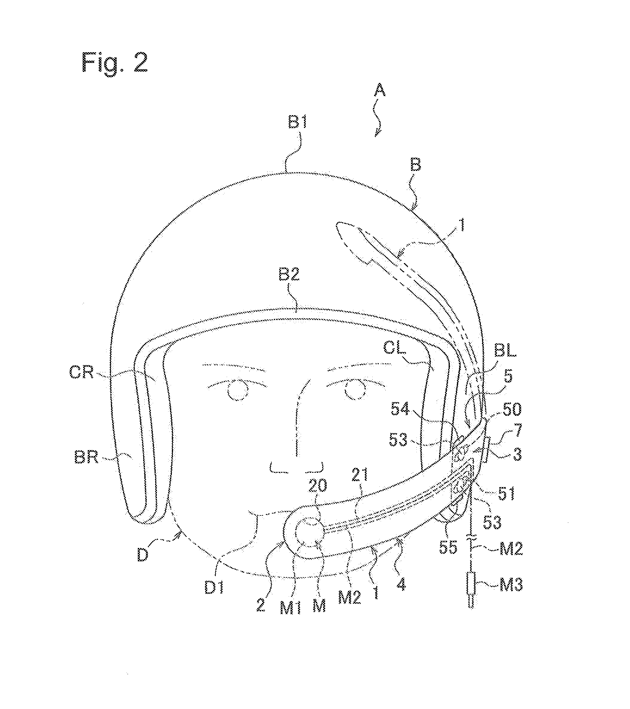
[0026]The following is description of an open-face helmet (hereinafter, “helmet”) A which provides a mounting device 1 of the first embodiment in the present invention referring to the drawings, FIGS. 1-4. It should be noted that each embodiment set forth below does not limit the scope of the present invention.
[0027]The helmet A provides an impact absorbing liner (not shown) molded with a foamed polystyrene material or a material having equivalent deformation function to the foamed polystyrene materials on the inner surface of the head B1 of a helmet shell B molded to the shape of an open-face helmet with a reinforced fiber material, a head pad (not shown) formed with such as an urethane material disposed inside the impact absorbing liner, cheek pads CL, CR (refer to FIG. 2) equipped to be removable on the inner surface of the right and left side parts BL, BR corresponding to the cheeks of the helmet shell B respectively, and a mounting device 1 supported about an axis at the left p...
second embodiment
[0049]FIG. 4 is a configuring diagram of a mounting device 1′ in the Descriptions of regions overlapping to the mounting device 1 are omitted by designating the same signs.
[0050]The mounting device 1′ is formed in a shape same as of the aforementioned mounting device 1, and a coating material 11 coats the mounting device 1′ with foamed synthetic resin materials having deformation function for the wearer D and suppleness around a plate-like core material 10 formed with a rigid synthetic resin material generating the repulsive resilience against deforming stress over the supporting part 3 to the mounting part 2 via the arm part 4.
[0051]Such the mounting device 1′ may be attached to the helmet A via the base plate 5 similar to the mounting device 1, and the same effects are expected as in the mounting device 1 by attaching to the helmet A.
[0052]Further, the mounting device 1′ maintains its shape by rigidity of the core material 10 made of rigid synthetic resin materials, so that thick...
third embodiment
[0054]FIG. 5 is a configuring diagram of a helmet A which provides the mounting device 1″ in the Descriptions of regions overlapping to the mounting device 1 are omitted by designating the same signs.
[0055]The mounting device 1″ is formed to be attached over the left to right side parts BL, BR of the helmet shell B. The supporting part 3L supported at the left side part BL via a base plate 5L and an arm part 4L connecting the supporting part 3L with the mounting part 2 are formed at the left side of the mounting part 2 arranged in the center when seen from the wearer side, and a supporting part 3R supported at the right side BR via a base plate 5R and an arm part 4R connecting the supporting part 3R with the mounting part 2 are formed at the right side of the mounting part 2.
[0056]Also, two mounting grooves 21L, 21R are formed in the mounting device 1″, the mounting groove 21L linked to the left of a mounting hole 20 and the mounting groove 21R linked to the right of the mounting h...
PUM
 Abstract
Description
Claims
Application Information
 - R&D
- Intellectual Property
- Life Sciences
- Materials
- Tech Scout
- Unparalleled Data Quality
- Higher Quality Content
- 60% Fewer Hallucinations
Browse by: Latest US Patents, China's latest patents, Technical Efficacy Thesaurus, Application Domain, Technology Topic, Popular Technical Reports.
© 2025 PatSnap. All rights reserved.Legal|Privacy policy|Modern Slavery Act Transparency Statement|Sitemap|About US| Contact US: help@patsnap.com


