Bending head for bending rod- and pipe-shaped workpieces

a technology for bending head and workpiece, which is applied in the field of bending head for bending rod-shaped and tubular workpieces, can solve the problems of not being able to produce complex components, not being able to bend very flexible, and complicated structure, etc., and achieves the effects of reducing space requirements, less complex structure, and producing very complex bending parts

Active Publication Date: 2014-01-02
WAFIOS AKTIENGES
View PDF3 Cites 23 Cited by
  • Summary
  • Abstract
  • Description
  • Claims
  • Application Information

AI Technical Summary

Benefits of technology

[0009]A feature and advantage of embodiments of the invention where the arrangement of the retaining bodies of all the tools and of the bending mandrel concentrically inside one another results in a telescope-like overall arrangement with minimal space requirement, which is also promoted by the fact that every tool consists of a retaining body with a bending pin protruding at its radial end face. Since, as a rule, its diameter is not very large, the wall thickness of the retaining body to which the bending pin is secured can likewise also be designed relatively small in radial direction, with the result that, in conjunction with the concentric arrangement of the retaining bodies and of the bending mandrel, as a whole a very much smaller space requirement results for the bending head according to the invention than in the case of the generic bending head.
[0022]Advantageously, the second plate also carries a third rotary drive by means of which the retaining unit for the radially innermost bending pin can be driven in the rotational direction. This makes it possible to attach the drive for the retaining unit for the radially innermost bending pin inside the whole device, in a particularly space-saving manner.

Problems solved by technology

Although this known bending machine allows a bending of the workpiece in two opposite bending directions without changing the bending head, its structure is very complicated and it is not very flexible when a bending mandrel is used once fitted, wherein complex components are also not producible.
With this known bending head, a bending of tubular workpieces with very thin walls can be carried out in two bending directions without a large outlay, wherein however, here too, the bending of very complex bending parts is not possible.
This known bending head also allows the production of complicated bending shapes, but its overall structure is very complex with, at the same time, a very large space requirement.

Method used


Image

  • Bending head for bending rod- and pipe-shaped workpieces
  • Bending head for bending rod- and pipe-shaped workpieces
  • Bending head for bending rod- and pipe-shaped workpieces

Examples


Embodiment Construction

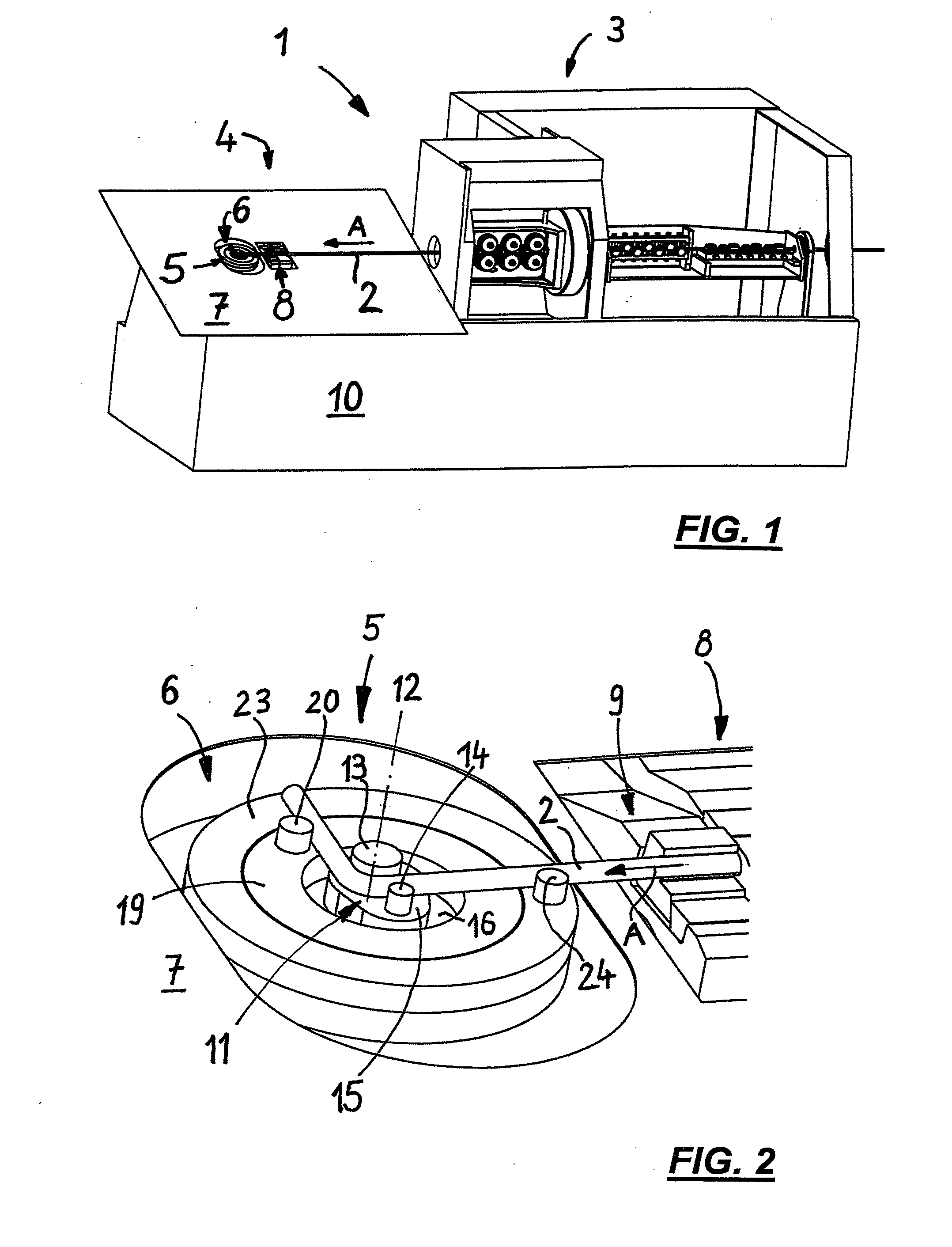
[0035]FIG. 1 shows, in a quite basic oblique view, a bending machine 1 for processing rod-shaped or tubular workpieces 2, which comprises a feed and straightening unit 3 as well as a bending unit 4 which is attached after the feed and straightening unit 3 in the direction of feed.

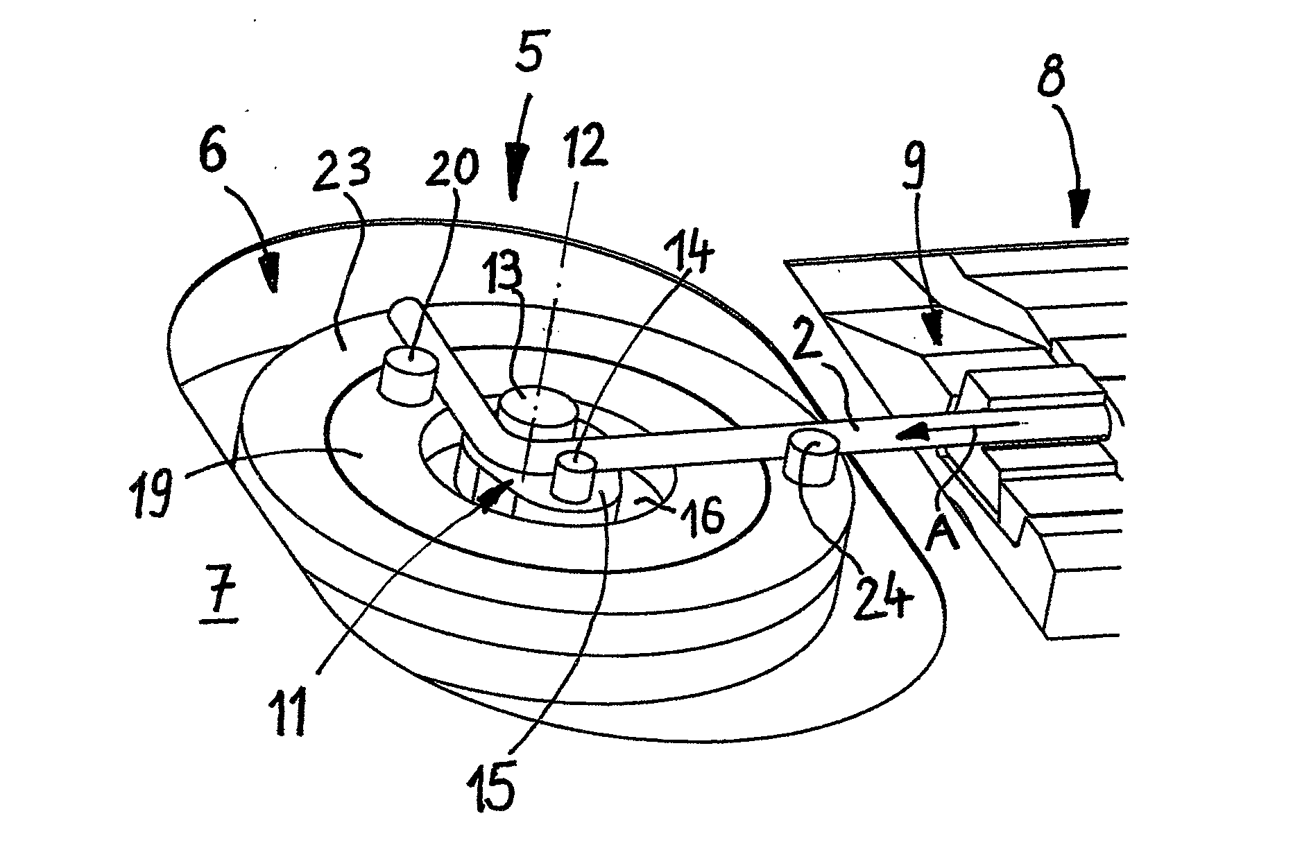
[0036]The bending unit 4 comprises a bending head 5 which is attached inside a recess 6 in a bending table 7.

[0037]The workpiece 2 is fed in, in the direction of the arrow A, by the feed and straightening unit 3 firstly to a guiding device 8, upstream of the bending head 5, in which a cutting device 9 (FIGS. 1 and 2) is also provided.

[0038]Bending table 7 as well as feed and straightening unit 3 sit on a lower frame 10. The bending table 7 is arranged at an angle to the mounting base in order to make it possible for the workpiece 2 to slide down after processing. However, no device is shown in FIG. 1 for receiving the processed workpieces 2 sliding down.

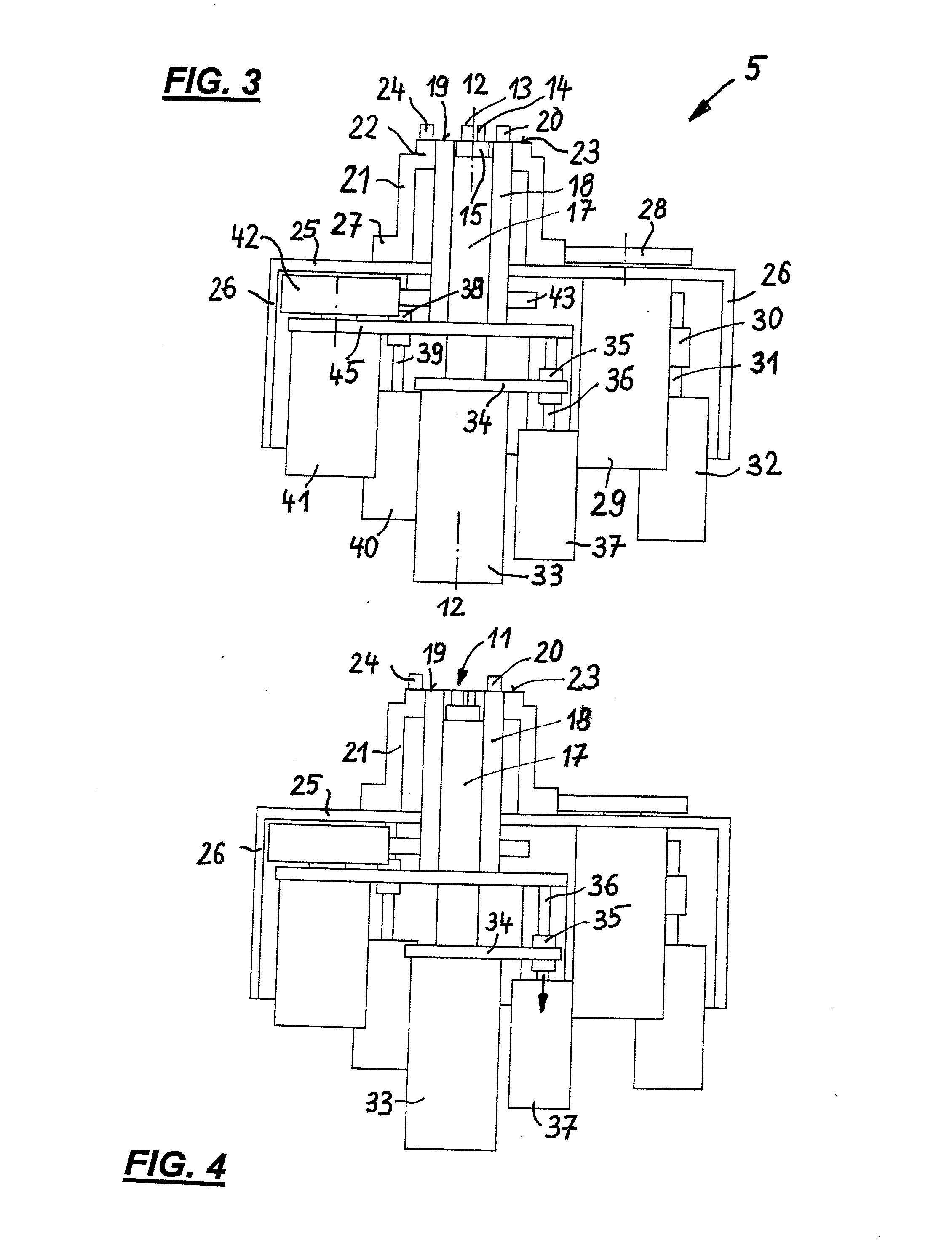
[0039]The bending head 5 represented in FIG. 2 in an e...


PUM

PropertyMeasurementUnit
angleaaaaaaaaaa
distanceaaaaaaaaaa
Bendingaaaaaaaaaa

Abstract

In a bending head for bending rod-shaped and tubular workpieces, with a retainer that can be rotated about a rotational axis and that carries a bending mandrel at one axial end, and with at least two further tools, which each comprise a retaining body with, at its axial end facing the bending mandrel, a bending pin and which can each be rotated—in each case independently of the other tools—the retaining bodies of the tools are arranged concentrically to the retainer of the bending mandrel and pivotable about its rotational axis.

Description

PRIORITY CLAIM[0001]The present application is a National Phase entry of PCT Application No. PCT / EP2012 / 000144, filed Jan. 13, 2012, which claims priority from German Application Number 102011015570.8, filed Mar. 30, 2011, the disclosures of which are hereby incorporated by reference herein in their entirety.FIELD OF THE INVENTION[0002]The invention relates to a bending head for bending rod-shaped and tubular workpieces.BACKGROUND OF THE INVENTION[0003]From EP 1 591 174 B1, a bending head for a bending apparatus for rod-shaped and tubular workpieces is known, in which the workpiece is clamped between a central bending mandrel and a clamping device movable relative to the latter, and is bent by pivoting the bending mandrel and the clamping device while the workpiece is clamped. This known bending head functions with several rotational axes, one of which serves to rotate the bending mandrel, while another is allocated to the pivoting of the clamping device. A further rotational axis i...

Claims


Application Information

Patent Timeline
Patent Type & Authority Applications(United States)
IPC IPC(8): B21F1/00
CPCB21F1/00B21D7/024
Inventor FRIES, STEFANMOCK, JORGWEIBLEN, FRANKBAIER, CARINA
Owner WAFIOS AKTIENGES
Why Eureka
Try Eureka