All-in-one-egr

a technology of air ducting and internal combustion engine, which is applied in the direction of combustion-air/fuel-air treatment, machine/engine, fuel air intake, etc., can solve the problems of increased space requirement, increased number of parts, and high weight, and achieves low weight, minimal space requirement, and simple and compact design

Active Publication Date: 2016-04-07
HANON SYST
View PDF1 Cites 15 Cited by
  • Summary
  • Abstract
  • Description
  • Claims
  • Application Information

AI Technical Summary

Benefits of technology

[0016]The problem which the invention proposes to solve consists in providing a device for exhaust gas recirculation for a system for air ducting of an internal combustion engine. The device should have a simple and compact design with a minimum number of components with minimal space requirement and a low weight, with at least the same number of application options as in the prior art. Furthermore, the costs of fabrication, maintenance and installation of the device should be minimal.

Problems solved by technology

The separate configuration of the components results in an increased number of parts, an increased space requirement, a high weight, and increased manufacturing costs and installation costs.

Method used


Image

  • All-in-one-egr
  • All-in-one-egr
  • All-in-one-egr

Examples


Embodiment Construction

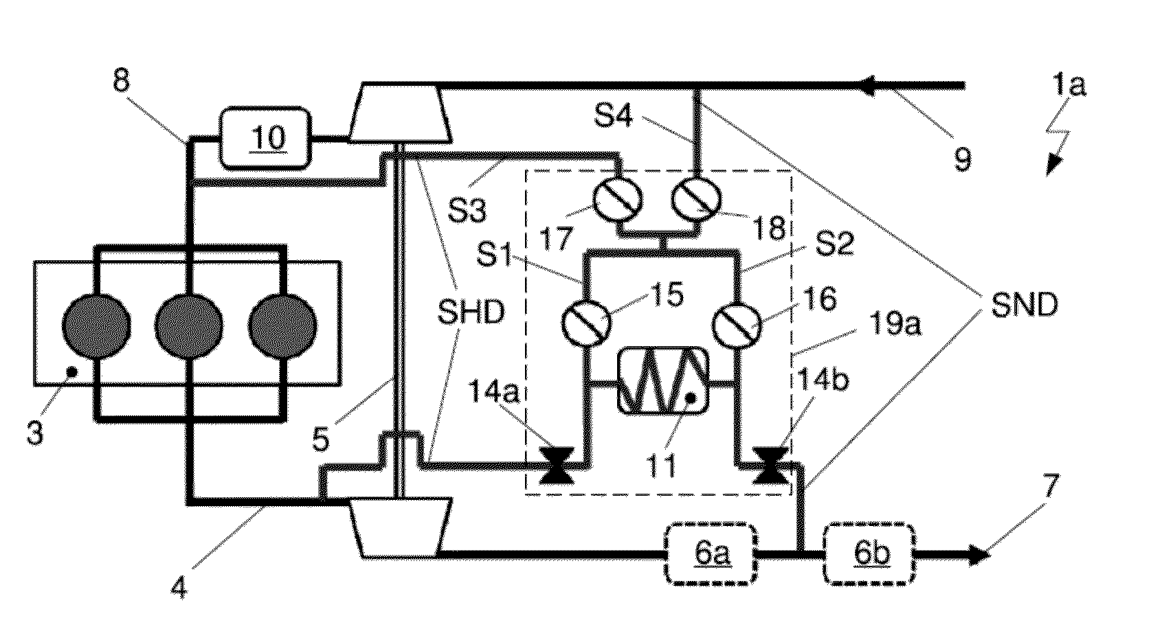
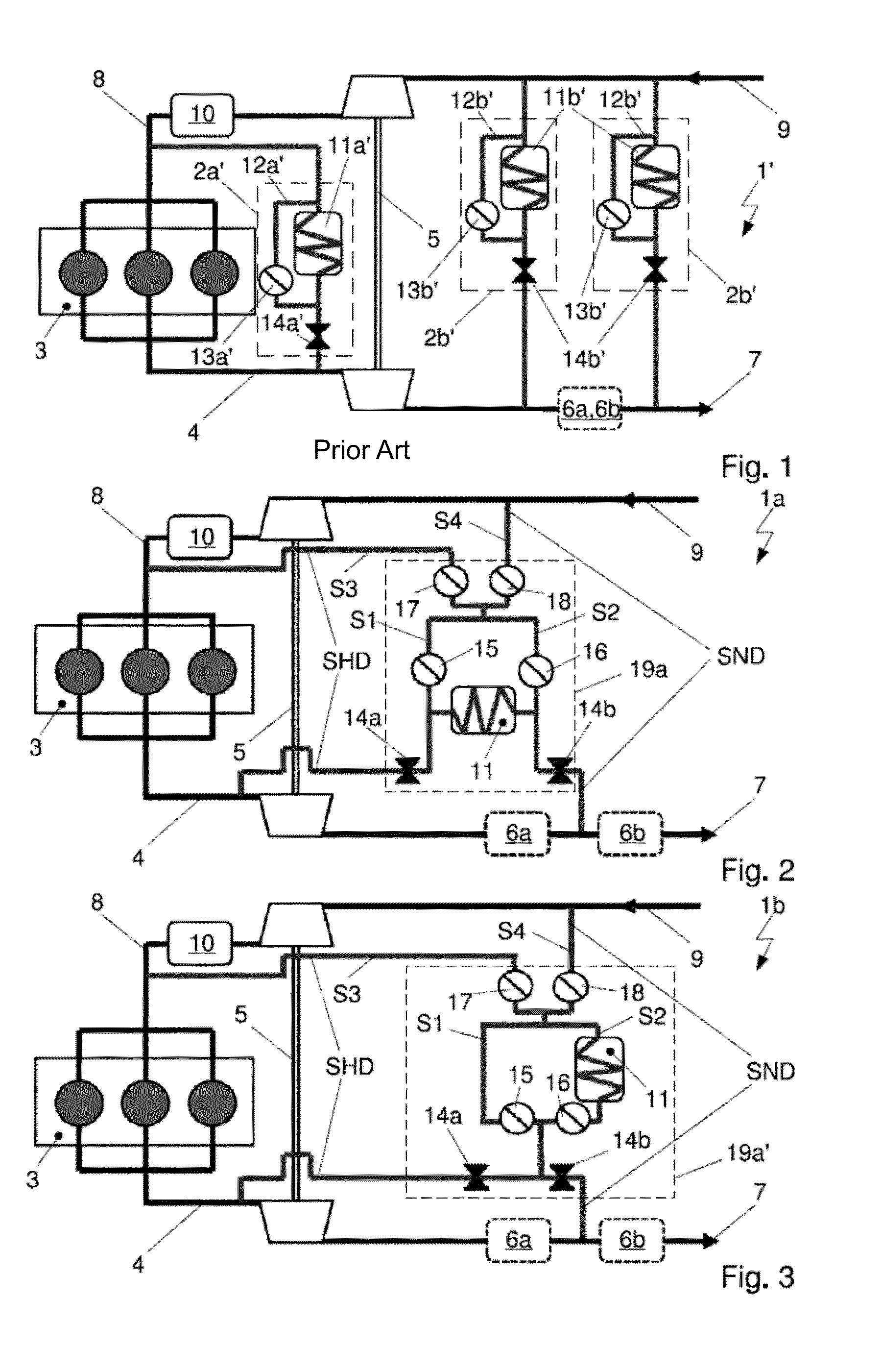
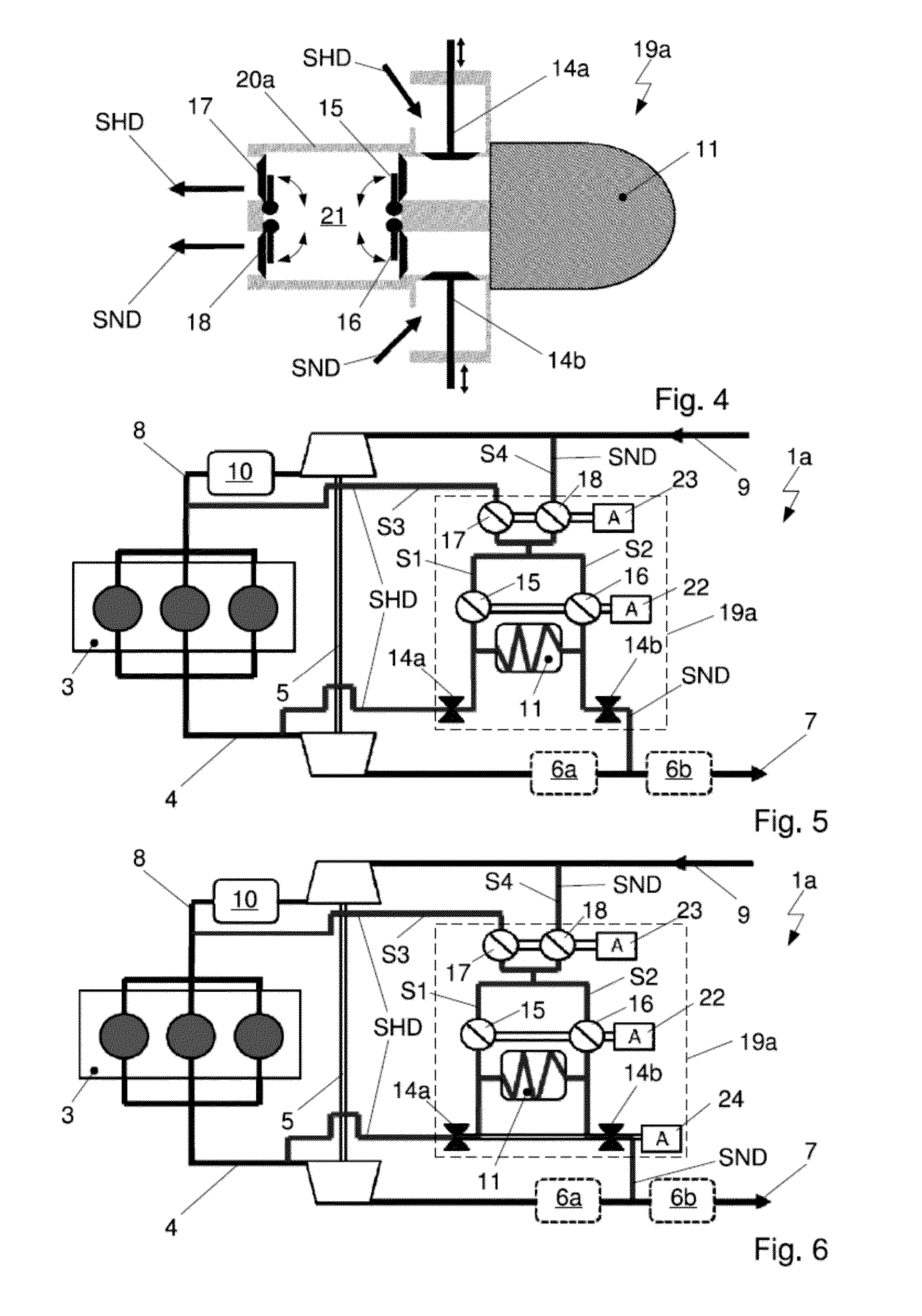
[0073]FIGS. 2 and 3 each show a system 1a, 1b for recirculation of exhaust gas of an internal combustion engine 3 with a device for exhaust gas recirculation 19a, 19a′ at high pressure and / or low pressure with four flow pathways S1, S2, S3, S4 and valves 15, 16, 17, 18 arranged in the flow pathways S1, S2, S3, S4 as well as an exhaust gas heat exchanger 11.

[0074]Through the intake line 8, fresh air as well as the exhaust gas is taken in from the surroundings across the compressor side of the turbocharger 5 in the flow direction 9 as combustion air for the internal combustion engine 3. The air, compressed by flowing through the compressor side of the turbocharger 5, is ducted across the charge air cooler 10 to the internal combustion engine 3 and distributed among the individual cylinders.

[0075]The exhaust gas produced by the combustion is ducted through the exhaust gas line 4 across the turbine side of the turbocharger 5. Since the turbine side is mechanically coupled, for example b...


PUM


Abstract

A device of a system for air ducting of an internal combustion engine in a motor vehicle with a turbocharger arranged between an exhaust gas line and an intake line. The device includes a high pressure flow pathway with a valve branching from the exhaust gas line between the internal combustion engine and a turbine side of the turbocharger, a low pressure flow pathway with a valve branching in the flow direction of the exhaust gas downstream from the turbine side of the turbocharger, and an exhaust gas heat exchanger. A first flow pathway with a valve and a second flow pathway with a valve merge into a mouth region with a third flow pathway. At least one section of the high pressure flow pathway, the low pressure flow pathway, the flow pathways, and the exhaust gas heat exchanger are integrated inside a housing formed as a continuous compact unit.

Description

CROSS-REFERENCE TO RELATED APPLICATION[0001]This patent application claims priority to German Non-Provisional Patent Application Serial No. DE 102014114507.0 filed Oct. 7, 2014 and German Non-Provisional Patent Application Serial No. DE 102015114356.9 filed Aug. 28, 2015. The disclosures of the above patent applications are hereby incorporated herein by reference in their entirety.FIELD OF THE INVENTION[0002]The invention concerns a device of a system for air ducting of an internal combustion engine in a motor vehicle. The system is configured with a turbocharger arranged between an exhaust gas line for the expansion of the exhaust gas and an intake line for the compression of the intake air. The device has a housing, a high pressure flow pathway branching off from the exhaust gas line between the internal combustion engine and a turbine side of the turbocharger with a valve, a low pressure flow pathway branching off in the flow direction of the exhaust gas downstream from the turbi...

Claims


Application Information

Patent Timeline
Patent Type & Authority Applications(United States)
IPC IPC(8): F02B37/22F01N3/02F02M35/10
CPCF02B37/225F01N3/02F02M35/10255F02M35/10157F02M26/05F02M26/06F02M26/09F02M26/23F02M26/25
Inventor OHREM, CARSTENDIEHL, PETERCUCUZ, STOJAN
Owner HANON SYST
Why Eureka
Try Eureka