

Frame for Electrolyser Module and Electrolyser Module and Electrolyser Incorporating Same
- Summary
- Abstract
- Description
- Claims
- Application Information
AI Technical Summary
Benefits of technology
Problems solved by technology
Method used
Image

Examples
Embodiment Construction
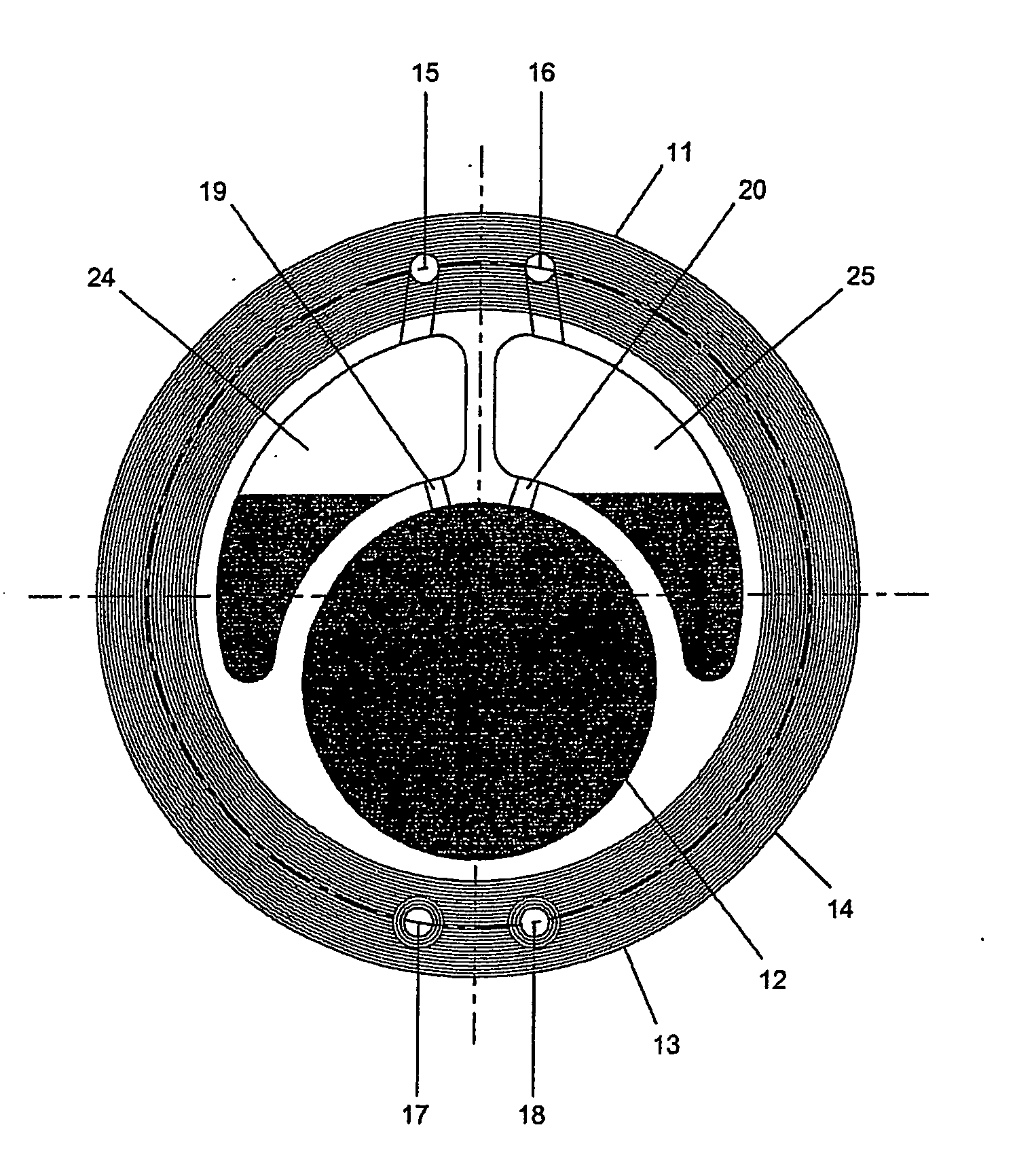
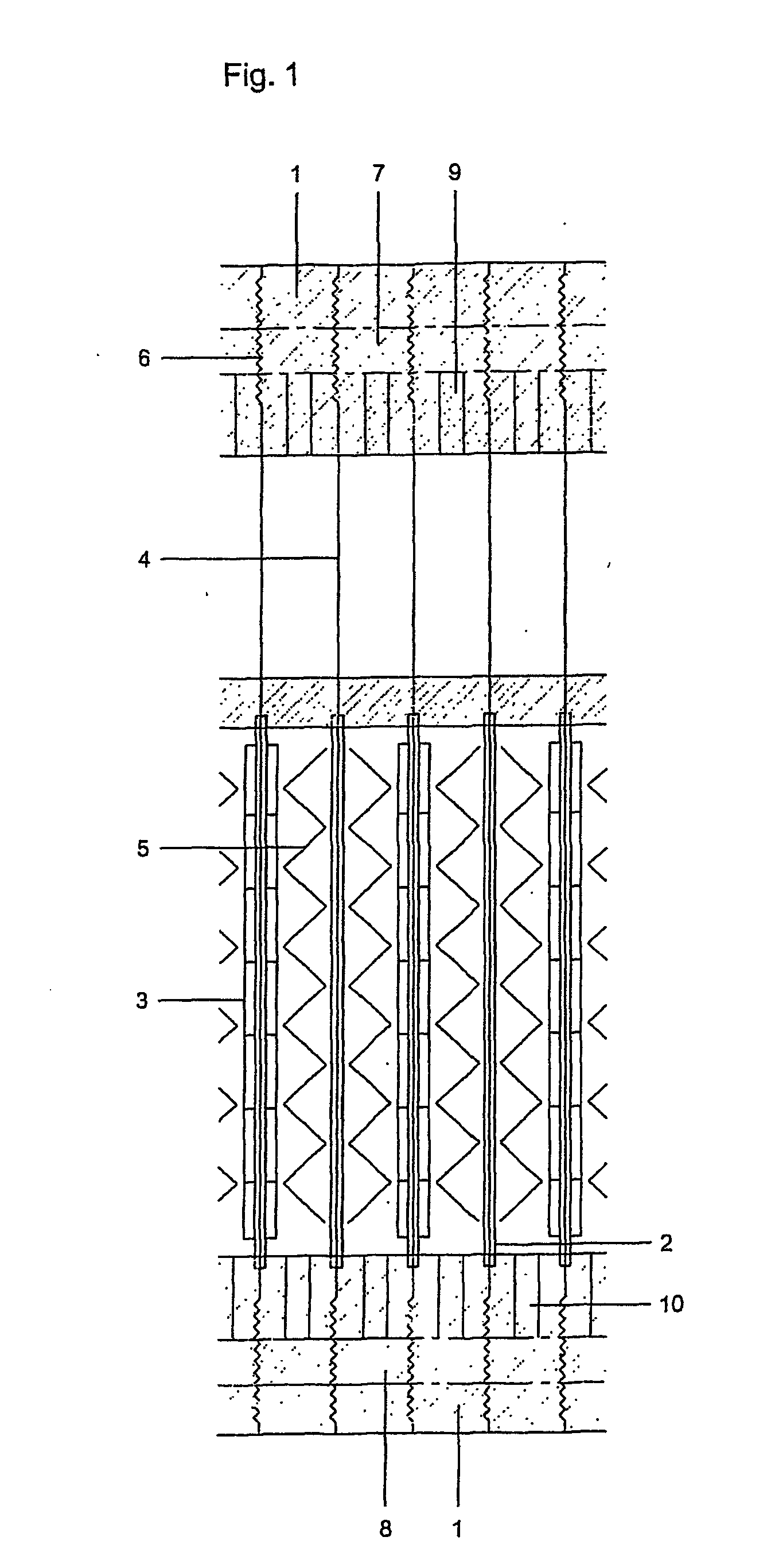
[0053] The electrolysis chambers in the electrolyser modules according to the invention contain one or more, preferably two electrodes placed vertically in the chamber. The electrodes are made of art-known materials that are inert to the electrolyte. The chambers are separated by a semi-permeable membrane or diaphragm and where two electrodes per chamber are used, the electrodes are preferably pressed against the membrane or diaphragm and connected by a suitable conductor. In a preferred arrangement, a bipolar plate is placed between the two electrodes and electric contact is made by placing two metallic woven sheets between each electrode.
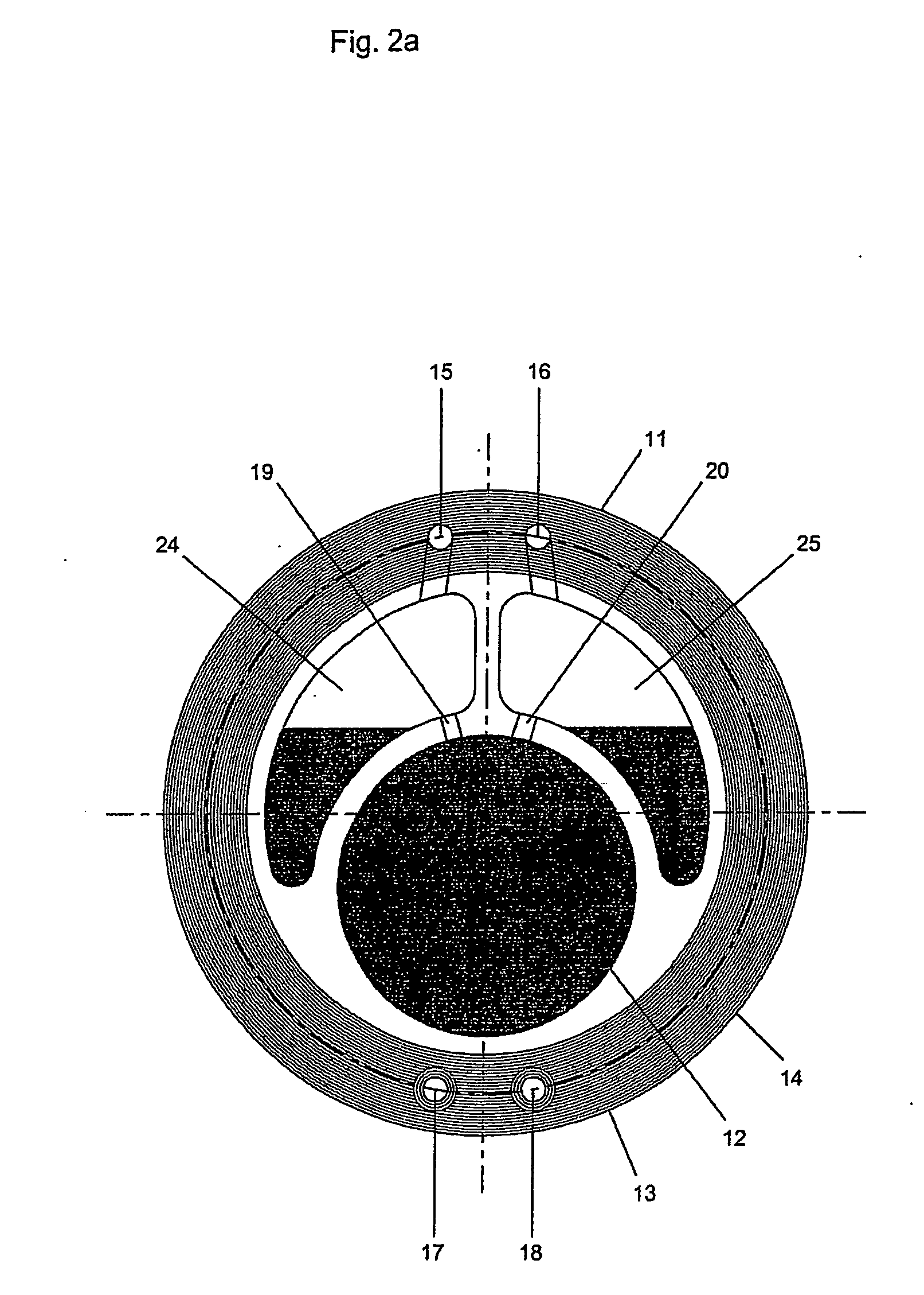
[0054] The various parts of each electrolysis chamber are held in a frame, i.e. the ‘holding frame’, which also forms the outer wall of the electrolysis chamber. As mentioned above, the holding frame may have various shapes, but preferably has a flat cylindrical (or ring) shape. In high pressure electrolyser modules, the holding frame is preferab...
PUM
| Property | Measurement | Unit |
|---|---|---|
| Pressure | aaaaa | aaaaa |
| Pressure | aaaaa | aaaaa |
| Structure | aaaaa | aaaaa |
Abstract
Description
Claims
Application Information