Electrical connector and connector assembly

a technology of electrical connectors and connector assemblies, applied in the direction of coupling device connections, coupling contact members, coupling parts engagement/disengagement, etc., can solve the problems of support mechanism being removed from its original position, and affecting the safety of the connector. , to achieve the effect of facilitating the locking and disassembly

Active Publication Date: 2010-04-29
APTIV TECH LTD
View PDF2 Cites 19 Cited by
  • Summary
  • Abstract
  • Description
  • Claims
  • Application Information

AI Technical Summary

Benefits of technology

[0008]To overcome the above drawbacks, the present invention aims at providing an electrical connector and connector assembly, which are capable of facilitating the locking and disconnecting of the assembly at every step of the assembling process.

Problems solved by technology

When engaging the connector that is engaged to one end of the wire harnesses with the corresponding connector that is installed at an electrical device component of a vehicle, a skilled person faces much difficulty in such an engagement process as these connectors should be installed within a limited space, e.g., the engine room of a vehicle.
However, since a conventional support mechanism is already in a completely engaged state when conveyed to a work place, a skilled person must disassemble the engagement support mechanism before engaging connectors, which adds more complexity to the process.
Further, after the completion of the engagement by the support mechanism, any carelessness in work procedures may cause the support mechanism to come off from its original position.
Moreover, when wiring conductive wires that are bound to the corresponding connector installed at an electrical device component, if a skilled person stretches the conductive wires for precise wiring, this may cause harm to the binding part, thereby causing damage to a connector.
In addition, in the prior art, a housing is configured to comprise both a terminal position assuring member assuring the precise position of the terminal and a receiving portion for receiving a protection plate protecting the terminal, thus it is inevitable that the size of the housing becomes large, and thereby increasing the volume of the connector assembly.

Method used


Image

  • Electrical connector and connector assembly
  • Electrical connector and connector assembly
  • Electrical connector and connector assembly

Examples


Embodiment Construction

[0029]Hereinafter, with reference to FIG. 1-9, various embodiments of an electrical connector according to the present invention will be described in details.

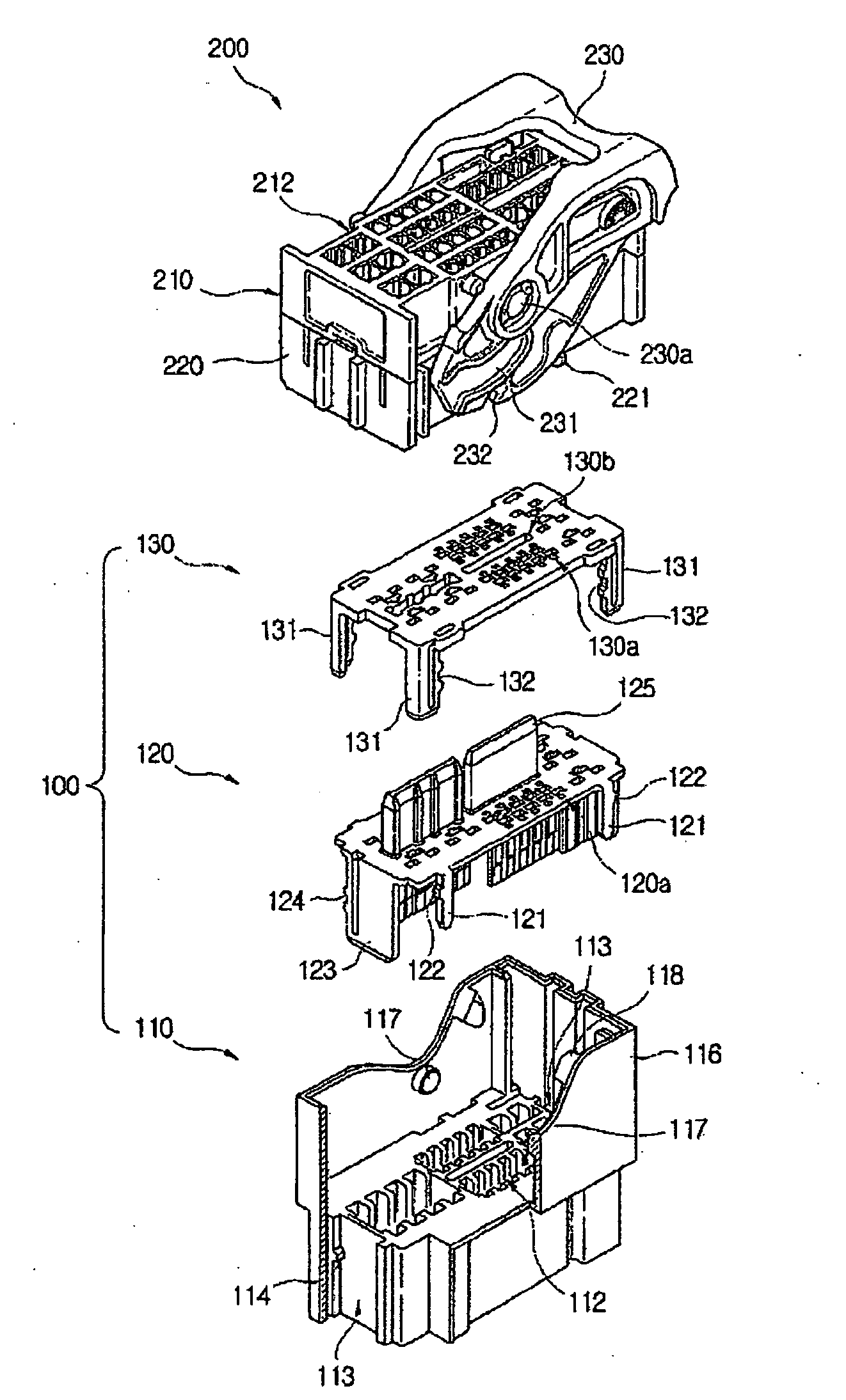
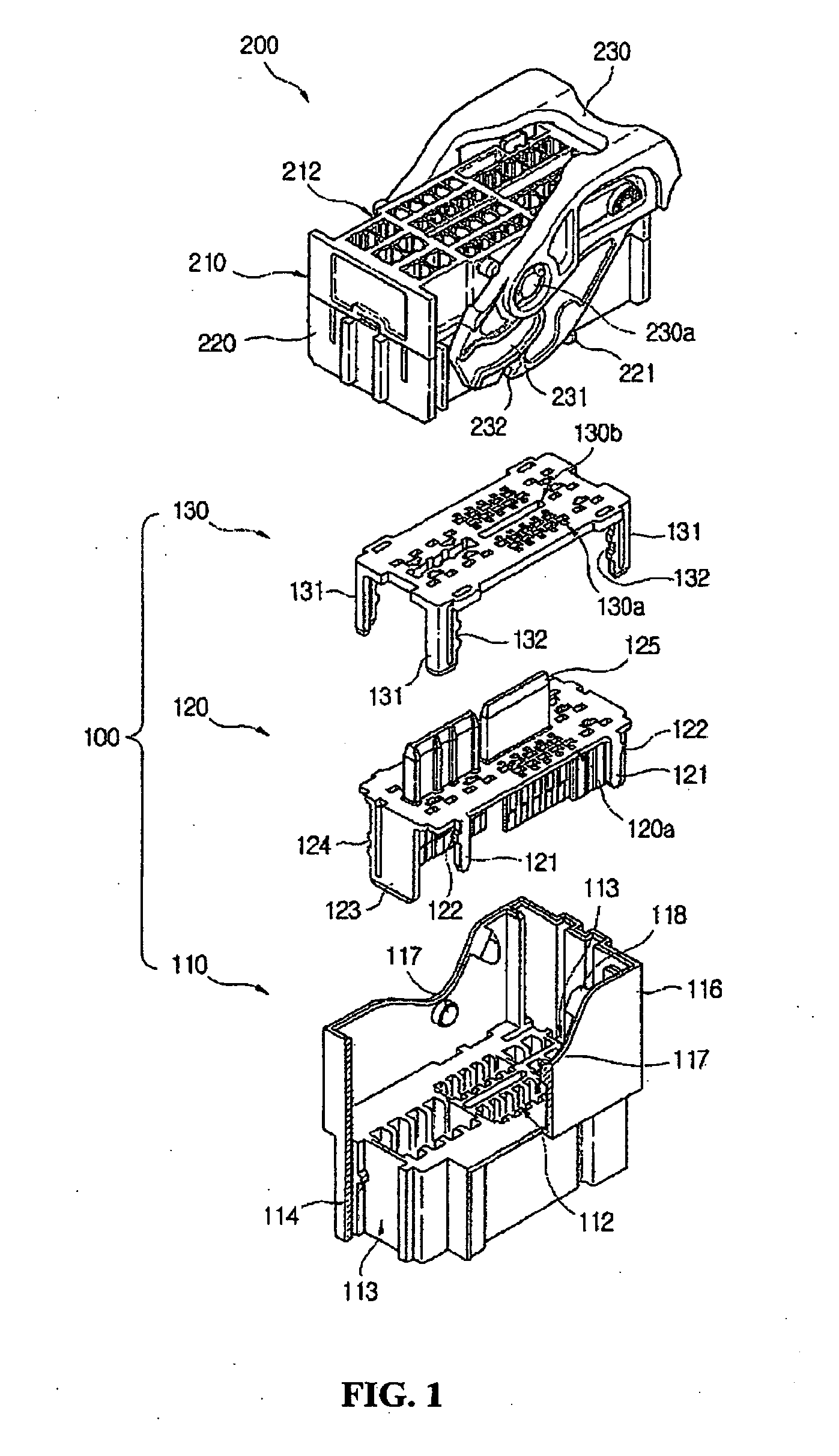
[0030]FIG. 1 is an exploded-perspective view showing a connector assembly according to the first embodiment of the present invention. The connector assembly includes a male connector (100) and a female connector (200) matable to each other.

[0031]The male connector of said connector assembly comprises a housing (110) having a plurality of male terminals and a number of terminal receiving holes (112) for receiving and supporting the male terminals therein; a terminal position assuring member (TPA: Terminal Position Assurance) (120) mounted to the housing (110), the terminal position assuring member including a plurality of first terminal passing holes (120a) configured so that one end (111a) of said terminals (111) passes therethrough; engaging means; and a terminal protecting plate (130) mounted to the terminal position assuring...


PUM


Abstract

The present invention relates to an electrical connector, which comprises means for preventing terminals from being deformed during connection of the connector. The electrical connector of the present invention comprises: a terminal position assuring member mounted to a connector housing; and a terminal protecting plate mounted to the terminal position assuring member. The terminal protecting plate comprises a first engaging element and the terminal position assuring member comprises a second engaging compactly configured since there is no need to provide any means for mounting or retaining the terminal protecting plate to the connector housing.

Description

[0001]This application claims priority from Republic of Korea patent application number 10-2006-114779, filed on 20 Nov. 2006, entitled “Electrical Connector And Connector Assembly”, which is hereby incorporated for reference.TECHNICAL FIELD[0002]The present invention relates to an electrical connector, and particularly relates to an electrical connector that is employed in connecting an electrical system to a central control unit of a vehicle, etc.BACKGROUND[0003]Generally, an electrical connection apparatus, which is conventionally known as a connector, is installed at a portion of an electrical system for transmitting power source, electrical signal or information, and connects two separated wires. Such a connector configured for connecting two separated wires comprises female and male connectors, wherein female or male terminals are provided inside of each connector such that the female and male terminals contact each other, thereby achieving electrical connections. Such an elec...

Claims


Application Information

Patent Timeline
Patent Type & Authority Applications(United States)
IPC IPC(8): H01R13/514
CPCH01R13/40H01R13/62938H01R13/4538H01R13/64H01R13/629
Inventor PARK, JOO HYUNJEONG, JAE HAN
Owner APTIV TECH LTD
Why Eureka
Try Eureka