Dispensing valve mounted on dispensing pumps

a technology of pump and dispensing valve, which is applied in the direction of piston pump, machine/engine, positive displacement liquid engine, etc., can solve the problems of two relatively expensive dispensing valves, and achieve the effect of easy cleaning

Inactive Publication Date: 2001-01-30
HASSIA VERPACKUNGSMASCHEN
View PDF3 Cites 14 Cited by
  • Summary
  • Abstract
  • Description
  • Claims
  • Application Information

AI Technical Summary

Benefits of technology

Proceeding from the dispensing valve of the aforementioned type, it is the object of the present invention--maintaining the advantages involved, including easy cleansing thereof--to so modify and improve a dispensing valve of the afore-de

Problems solved by technology

However, the disadvantage involved resides in that two of such relatively expensive dispensing valves will ha

Method used


Image

  • Dispensing valve mounted on dispensing pumps
  • Dispensing valve mounted on dispensing pumps
  • Dispensing valve mounted on dispensing pumps

Examples


Embodiment Construction

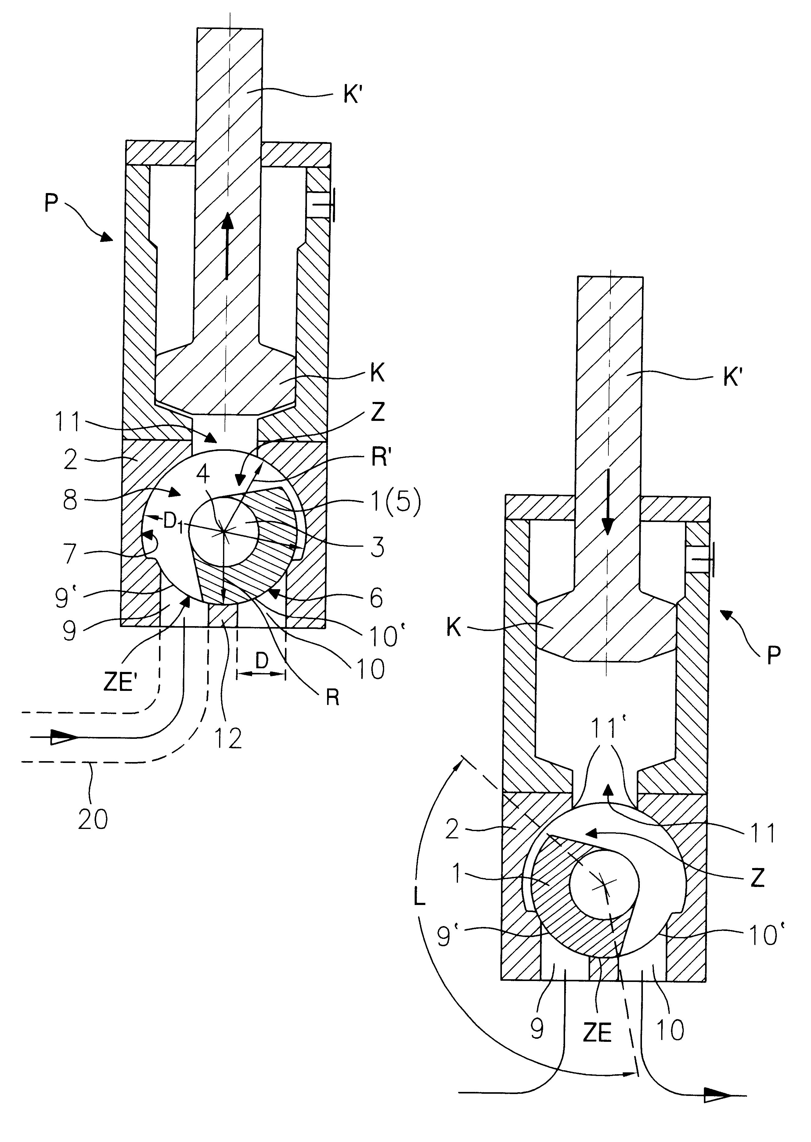
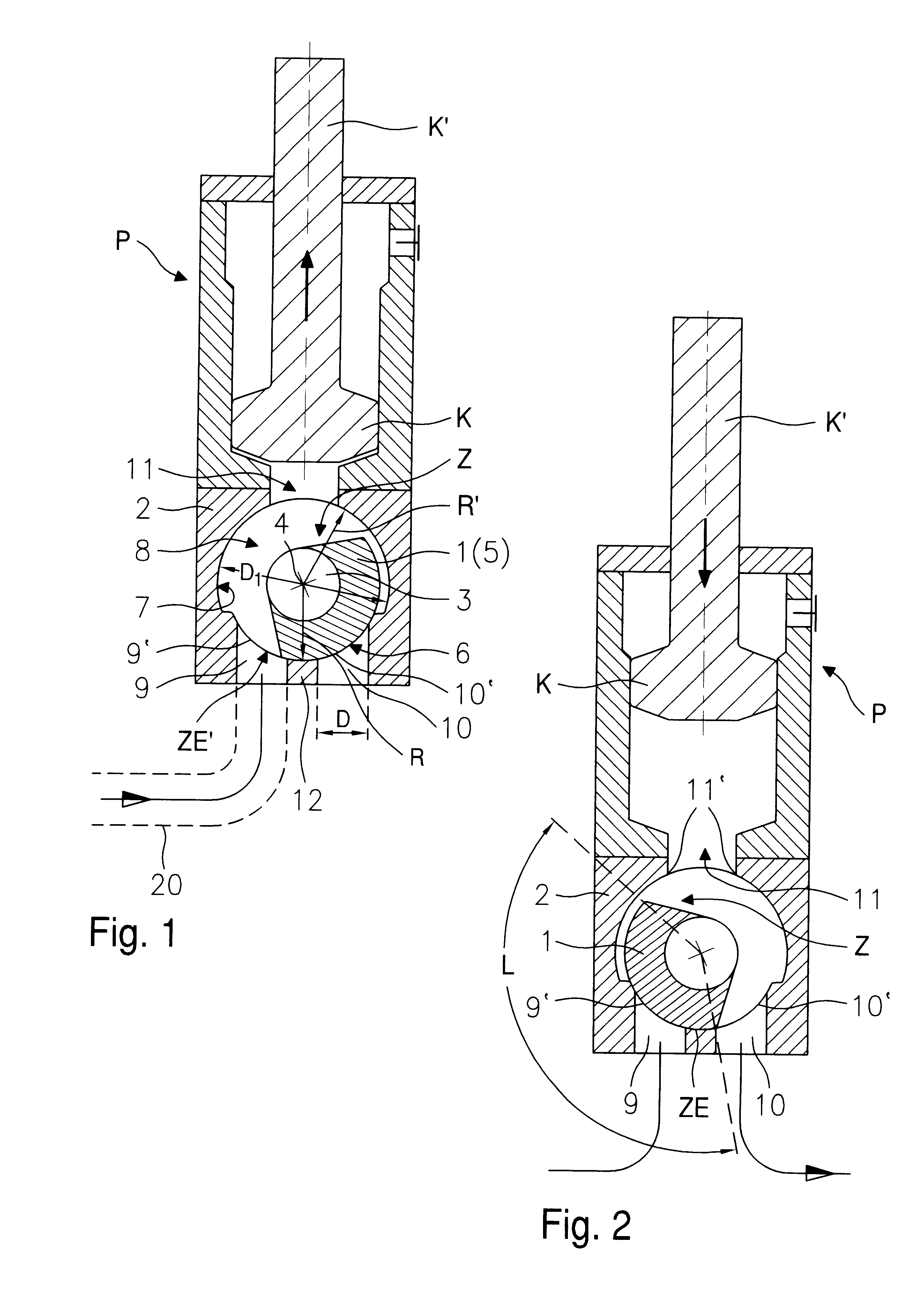
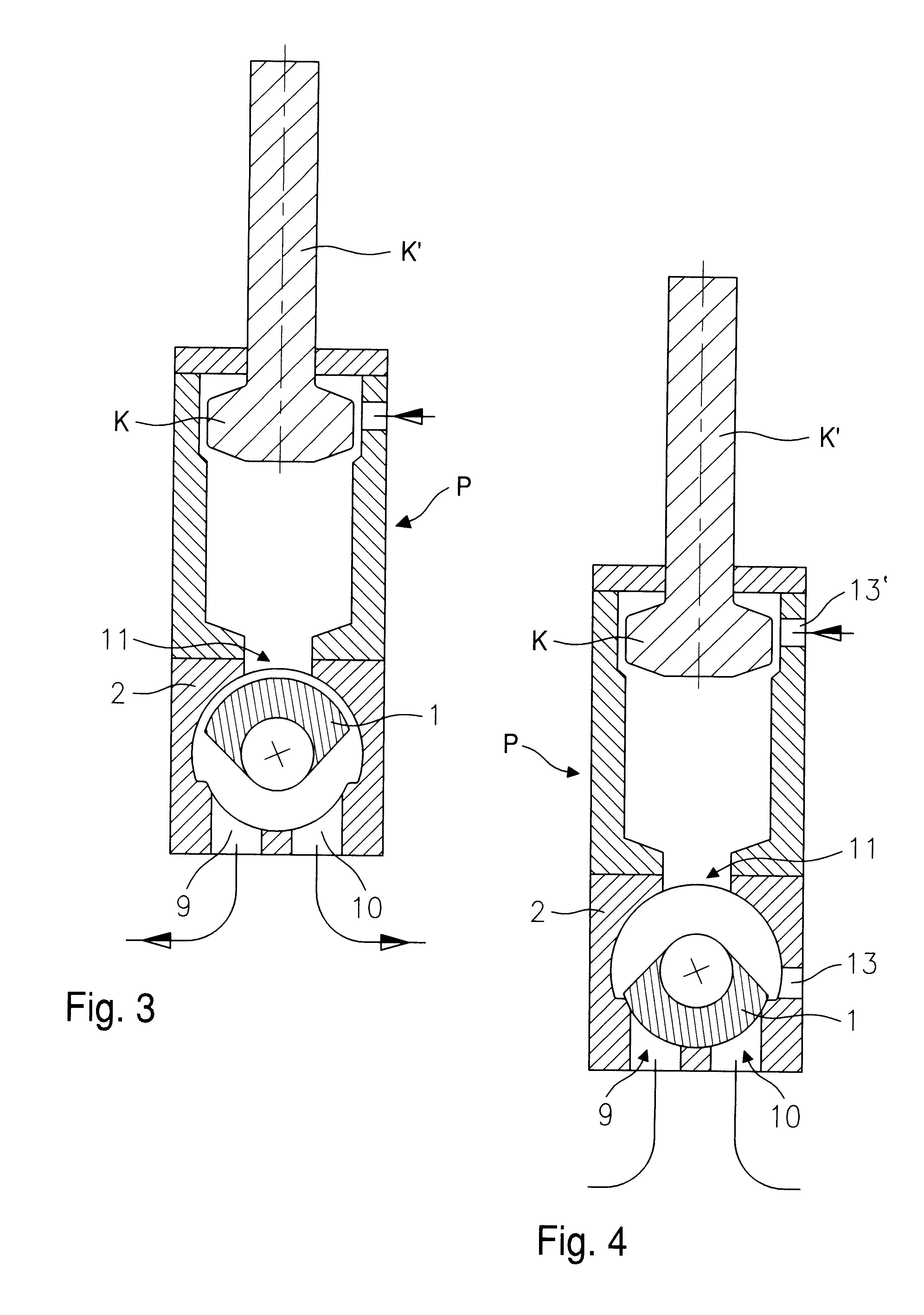
The dispensing valve especially intended for dispensing measured amounts of at least partially liquid material, such as jam, yogurt or the like, comprises a housing 2 provided with feeding and discharge channels 9, 10, a closing portion 1 swivable in a cylindrical cavity 8 of the housing 2 and having a larger diameter than the diameter D of the feeding and discharge channels 9,10. The said closing portion 1 is formed as a head of an adjusting shaft 3 sealingly protruding into the housing 2 and being of a smaller diameter than the diameter D1 of the cavity 8. The actual closing face 6 of the closing portion 1 extends in parallel to the cylindrical wall 7 of the cavity 8, and the closing portion 1 is in the form of a cam 5 which, relative to the swivel axis 4 of the adjusting shaft 3 is oriented toward one side. The radius R of the closing face 6 of the cam 5 is slightly smaller dimensioned than the radius R' of the cavity 8 externally of the area of the cylindrical plane ZE', in whic...


PUM


Abstract

A dispensing valve comprises a housing defining a cylindrical cavity and feeding and discharge channels communicating with the cavity respectively through feeding and discharge ports. The cylindrical cavity has a diameter larger than the diameter of the feeding and discharge channels and the feeding and discharge ports. A pump intake and ejection port communicates with the cavity, the feeding and discharge channels being arranged substantially opposite the pump intake and ejection port. A closing part comprises an adjusting shaft sealing protruding into the housing and rotatable about an axis, and a cam carried by the adjusting shaft for rotation in the cavity, the cam being oriented toward one side with respect to the adjusting shaft axis and having a closing face extending parallel to the cylindrical wall of the cavity and being rotatable in a cylindrical adjustment plane extending over the feeding and discharge ports. The closing face has a radius which is smaller than the radius of a portion of the cylindrical cavity wall outside the cylindrical adjustment plane, and the closing face has an arc length dimensioned so that the closing face closes the feeding and discharge ports in one rotary position of the cam and, in another rotary position, the closing face extends from one of the rims of the pump intake and ejection port to an inner rim of a respective one of the feeding and discharge ports.

Description

1. Field of the InventionThe present invention relates to a dispensing valve on dispensing pumps or to a combined dispensing pump valve for dispensing measured amounts of at least partially liquid material containing solid pieces, such as jam, yogurt or the like, into packaging containers.2. Description of the Prior ArtA dispensing valve of this type intended for the afore-mentioned use has been disclosed by German Patent No. 195 04 546. It is true, this prior art dispensing valve also operates like a so-called rotary slide valve (see, e.g. U.S. Pat. No. 3,228,412), however, the operation is such that the cam closes the inlet port like a finger held on an opening, with the said cam being swiveled for opening purposes, thereby releasing a relatively large portion of the housing space. The material dispensed in measured amounts can readily flow, with no plugging risk, about the cam which is in the opening position. The actual dispense in measured amounts is effected by a corresponding...

Claims


Application Information

Patent Timeline
IPC IPC(8): F04B7/00F04B13/00
CPCF04B7/0011F04B13/00
Inventor KURTH, GUNTER
Owner HASSIA VERPACKUNGSMASCHEN
Why Eureka
Try Eureka