
Cordless shade roller

a shade roller and cordless technology, applied in the direction of door/window protective devices, building components, construction, etc., can solve the problems of increased manufacturing cost, limited use/type of shade rollers, limited use/type of blinds, etc., and achieves the effect of reducing manufacturing and assembly costs, and reducing manufacturing costs

Inactive Publication Date: 2017-12-07
K E & KINGSTONE
View PDF2 Cites 14 Cited by
  • Summary
  • Abstract
  • Description
  • Claims
  • Application Information

AI Technical Summary

Benefits of technology

The present invention provides a cordless shade roller with a simple and standardized S-shaped constant force spring that reduces manufacturing and assembly costs and requires minimal space. This is the technical effect of the invention.

Problems solved by technology

Or the use / type of the shade is limited.
Thus the use / kind of the blind is limited.
Thereby the manufacturing cost is increased.
This has negative effect on mass production and production management of the S-shaped constant force spring.
Secondly, the respective S-shaped constant force spring of each blind has a plurality of components and complicated structure.
The assembly of the resilient unit 41 is getting difficult and more space required for installation of the resilient unit 41.
The conventional design of the S-shaped constant force spring has complicated structure, the problem of unable to be standardized, higher manufacturing and assembly cost and lower use efficiency, Thus there is room for improvement and a need to provide a novel design of the S-shaped constant force spring.

Method used


Image

  • Cordless shade roller
  • Cordless shade roller
  • Cordless shade roller

Examples


Embodiment Construction

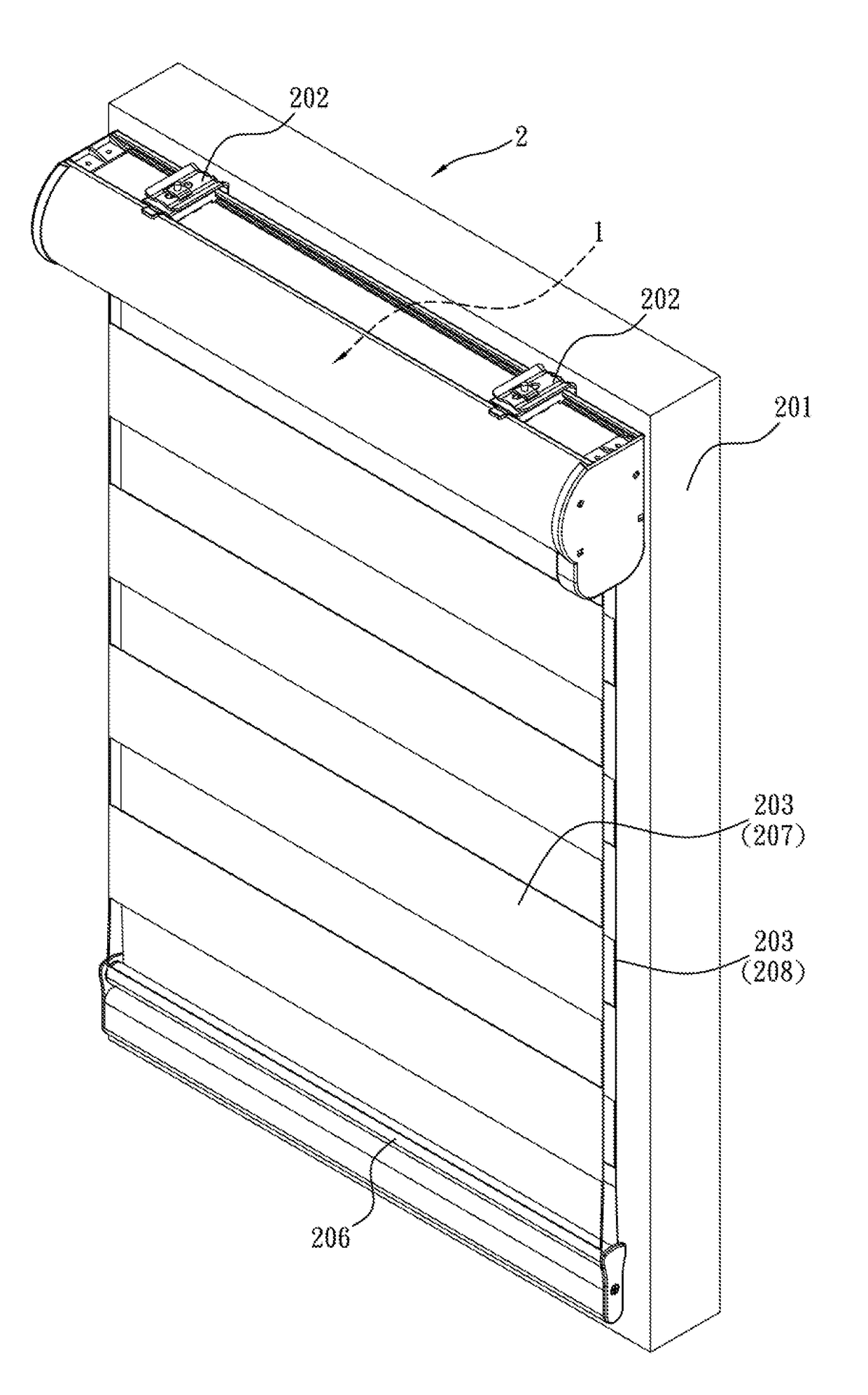
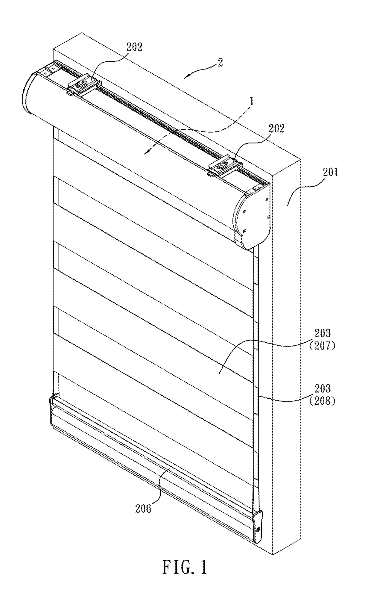
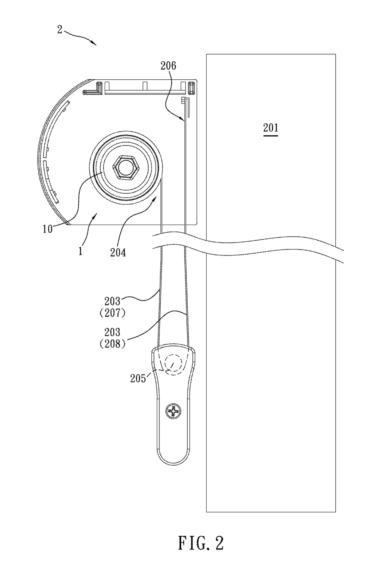
[0026]Refer from FIG. 1 to FIG. 5, a cordless shade roller 1 of the present invention is used in a blade-spring-type zebra shade 2.

[0027]The zebra shade includes a zebra fabric having transparent sections and non-transparent sections placed in parallel positions alternatively. The zebra fabric is used in combination with other accessories to form a front fabric and a rear fabric moved relative to each other. The overlapping of the transparent / non-transparent sections of the front / rear fabric can be adjusted by an operating mechanism. When the transparent sections of the front / rear fabric and the transparent sections of the rear / front fabric are completely overlapped and corresponding to each other, the shade is in a transparent state. Once the transparent sections of the front / rear fabric and the non-transparent sections of the rear / front fabric are completely overlapped and corresponding to each other, the shade is in a totally shaded (non-transparent) state. While the transparent / ...


PUM


Abstract

A cordless shade roller is revealed. The cordless shade roller includes a roller tube, a passive-end bracket set on a first end of the roller tube, and an active-end bracket disposed on a second end of the roller tube. The active-end bracket is a cap formed by assembly of a first cover with a second cover and having a narrow space therein. An S-shaped constant force spring is clipped in the narrow space of the cap. The S-shaped constant force spring consists of a first wound roll used as a storage drum, a second wound roll used as an output drum, and an S-shaped spring strip wound around the first wound roll and the second wound roll reversibly. No baffle is disposed on each of two sides of the first wound roll and of the second wound roll.

Description

BACKGROUND OF THE INVENTION[0001]The present invention relates to a cordless shade roller, especially to a cordless shade roller in which a cord for retraction or extension of the shade is replaced by an S-shaped constant force spring.[0002]Cordless shades are common shades designed for prevention of strangulation hazard to children from conventional shade cords. Refer to U.S. Pat. No. 5,787,952, U.S. Pat. No. 324,135, U.S. Pat. No. 2,868,285, U.S. Pat. No. 6,474,394, and U.S. Pat. No. 8,251,120, these are all related to cordless shades. Most of them use an S-shaped constant-force spring (or spring-steel ribbon in U.S. Pat. No. 8,251,120) to replace the cord for retracting or extending a roller tube of the shades. The S-shaped constant-force spring generally includes an S-shaped spring wound around a first wheel (or storage drum in U.S. Pat. No. 6,474,394) and a second wheel (or output drum in U.S. Pat. No. 6,474,394) respectively. The structure of the S-shaped constant-force spring...

Claims


Application Information

Patent Timeline
Patent Type & Authority Applications(United States)
IPC IPC(8): E06B9/60E06B9/42E06B9/264E06B9/24E06B9/322
CPCE06B9/60E06B9/42E06B9/264E06B2009/3222E06B2009/2458E06B2009/2435E06B2009/2405
Inventor HUANG, WEN-CHONG
Owner K E & KINGSTONE
Learn More