
Adjustable Gas Cyclic Regulator for an Autoloading Firearm

Inactive Publication Date: 2014-01-02
F & D DEFENSE
View PDF11 Cites 5 Cited by
  • Summary
  • Abstract
  • Description
  • Claims
  • Application Information

AI Technical Summary

Benefits of technology

The present invention is a gas valve with a delay mechanism that allows firearms to have unlimited tuning of gas flow rate for different operating conditions. It reduces gas-flow turbulences and increases gas-cyclic efficiency, reducing felt-recoil, and improving accuracy and overall performance of the firearm. The gas valve has a regulator occupying a portion of the chamber to define a chamber operating volume, the regulator having at least one outer diameter corresponding to an inner diameter of the passage to substantially inhibit gas flow from the from the chamber therebetween.

Problems solved by technology

It is known, for example, that the addition of more gas into the operating systems increases the potential for failure of the autoloading mechanism.
While Noveske, ArmaLite, Spike Tactical, and JP Enterprises represent improvements over other systems that do not provide a mechanism for adjusting gas flow characteristics, Noveske does not provide fine, indiscrete tuning of such characteristics.
This causes the gas to immediately lose significant amount energy while turning ninety-degrees toward the piston assembly, and negatively affects the gas-cyclic efficiency and overall performance of the autoloading firearm.
When using different bullet types, weights, and load charges, the pressures created by the bullet discharge may fall outside that range, effectively meaning that the firearm will not properly cycle with all loads.
Systems such as Noveske, however, do not provide the user with the ability for tuning of the auto-loading mechanism of such high-precision firearms.

Method used


Image

  • Adjustable Gas Cyclic Regulator for an Autoloading Firearm
  • Adjustable Gas Cyclic Regulator for an Autoloading Firearm
  • Adjustable Gas Cyclic Regulator for an Autoloading Firearm

Examples


Embodiment Construction

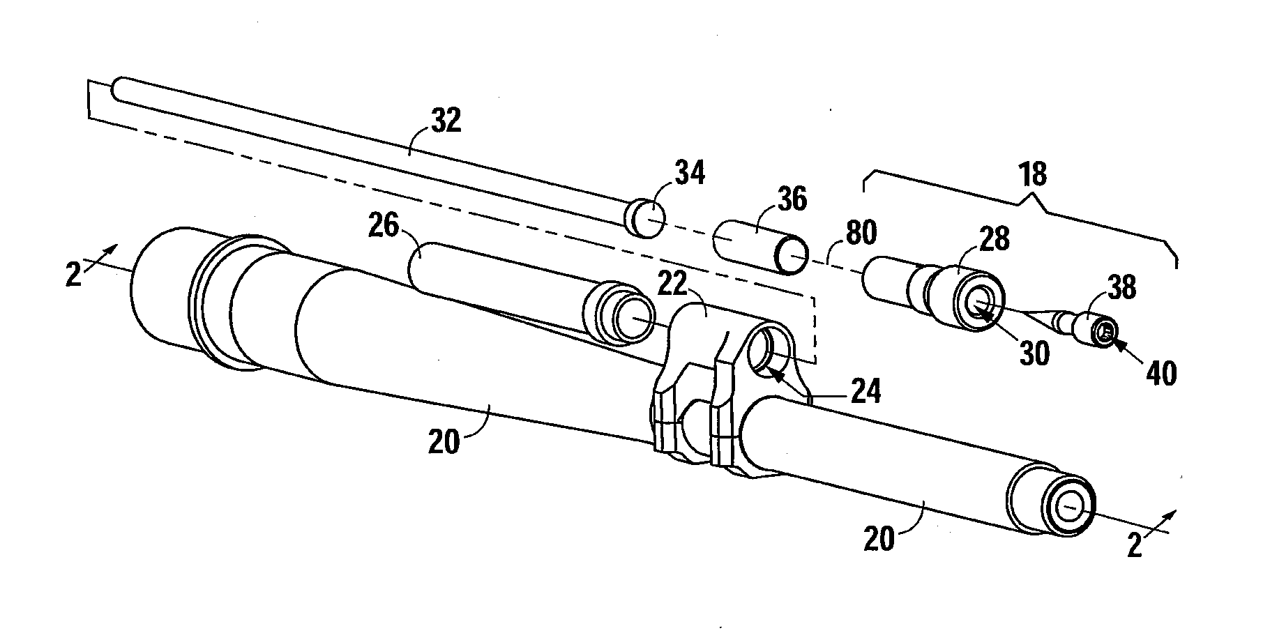
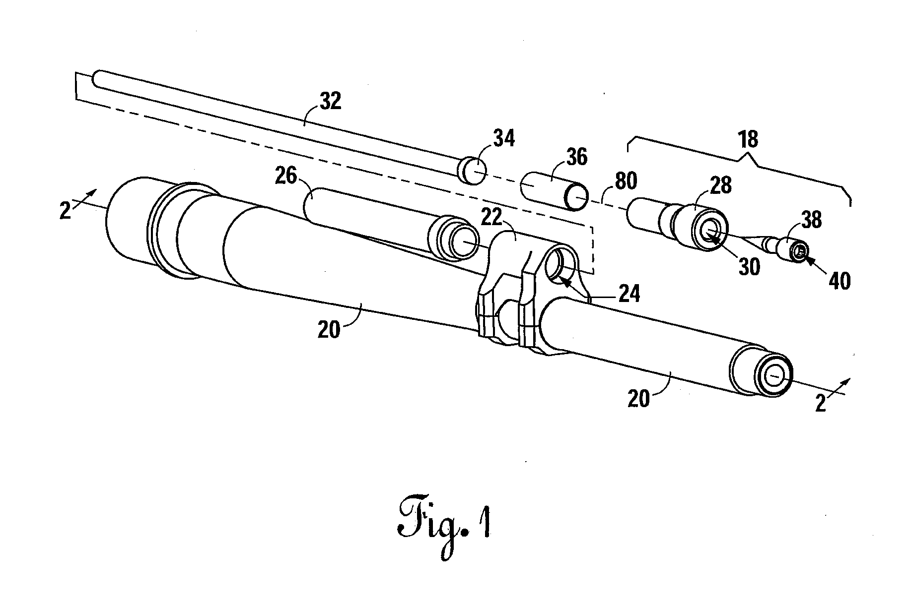
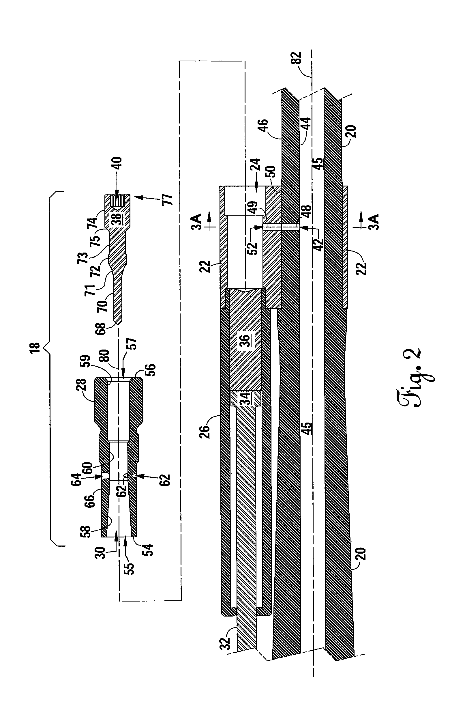
[0023]FIG. 1 shows an embodiment 18 of the present invention in connection with components of an autoloading firearm having a barrel 20. The autoloading components include a gas block 22 attached around the barrel 20 that defines a generally cylindrical interior 24, and a gas tube 26 coupled to the gas block 22. A piston rod 32 has a head 34 movable within the gas tube 26. A piston member 36 is also positioned within the gas tube 26 adjacent the piston rod 32 and the gas valve 28. The gas tube 26 is a generally cylindrical hollow body having a partially closed end allowing the piston rod 32 and piston member 36 to cycle therewithin, with the opposing end of the piston rod 32 connected to the remainder of the autoloading mechanism (not shown) to eject the spent casing and load a new round.

[0024]The embodiment 18 includes a gas valve 28 that defines a generally cylindrical gas chamber 30. The gas valve 28 is positioned within the interior 24 of the gas block 22. The gas valve 28 is lo...


PUM


Abstract

An adjustable gas valve having an annular body with an inner surface defining a gas chamber and first and second annular end surfaces defining first and second openings of said gas chamber, the gas valve further having outer surface and at least one gas channel extending between the inner surface and the outer surface providing a gas communication path from the outer surface to the gas chamber, wherein said at least one gas channel is orientated to direct fluid egressing from the channel into the chamber along the inner surface. The invention further includes a regulator occupying a portion of the chamber to define a chamber operating volume, the regulator having at least one outer diameter corresponding to an inner diameter of the passage to substantially inhibit gas flow from the pass through the second opening.

Description

CROSS-REFERENCES TO RELATED APPLICATIONS[0001]Not applicable.STATEMENT REGARDING FEDERALLY SPONSORED RESEARCH OR DEVELOPMENT[0002]Not applicable.BACKGROUND OF THE INVENTION[0003]1. Field of the Invention[0004]The present invention relates to autoloading firearms. More specifically, the invention is an apparatus for tuning the gas flow rate and / or timing of an autoloading firearm for different operating conditions.[0005]2. Description of the Related Art[0006]In the field of autoloading firearms, adjustable gas blocks provide means for compensating for regulated gas flow attributable to the use of silencers and various types of loads of ammunition. It is known, for example, that the addition of more gas into the operating systems increases the potential for failure of the autoloading mechanism. Particularly with high-precision autoloading firearms, the ability to fine tune the gas flow characteristics becomes even more important, as even minor differences between ammunition can affect...

Claims


Application Information

Patent Timeline
IPC IPC(8): F41A5/18F41A19/02
CPCF41A5/28F41A19/03
Inventor HALL, CORBY
Owner F & D DEFENSE
Learn More