
Recoil attenuated payload launcher system

a payload and attenuation technology, applied in the field of systems for discharging payloads, can solve the problems of difficult to bring traditional tools into action, the practical upper limit of further increasing the launcher and the cartridge diameter to increase the payload capacity, and the limited payload capacity of the launcher. to achieve the effect of reducing the recoil

Active Publication Date: 2014-08-19
POLYWAD
View PDF79 Cites 4 Cited by
  • Summary
  • Abstract
  • Description
  • Claims
  • Application Information

AI Technical Summary

Benefits of technology

This patent describes launcher systems that can be handheld or shoulder mounted, or carried and fired by an individual without being mounted. These systems reduce the recoil felt by the person launching the system through a variety of methods. One way they achieve this is by managing, distributing, and reducing the gas expansion-compression zone, which involves venting gas to reduce recoil. Additionally, these systems can use springs or pneumatic pressure to impart forward movement to the payload cartridge. The "technical effects" of these systems include reducing felt recoil, improving the stability and accuracy of the payload, and making the launching process more comfortable for the user.

Problems solved by technology

Even though these launchers use cartridges that are substantially larger than modern shotshell cartridges, their payload capacity is still limited.
Moreover, simple design principles suggest that further increasing launcher and cartridge diameter to increase payload capacity has a practical upper limit, beyond which increased recoil would effectively prohibit using the high capacity launchers in a handheld or shoulder mounted configuration.
These features can be important factors in the decision to carry such launchers into hazardous situations, where it is usually extremely difficult to bring traditional tools into action.
For example, extremely dangerous combat or battlefield situations, law enforcement operations, and riots, constitute dangerous environments in which portability and ease of operation of a chemical, fire suppression, signaling, and related cartridges and launchers may be important.
Moreover, hand carried launching devices and their cartridges are limited in size due to one's ability to handle recoil, thereby limiting the overall amount of any particular payload that can be safely and accurately deployed.

Method used


Image

  • Recoil attenuated payload launcher system
  • Recoil attenuated payload launcher system
  • Recoil attenuated payload launcher system

Examples


Embodiment Construction

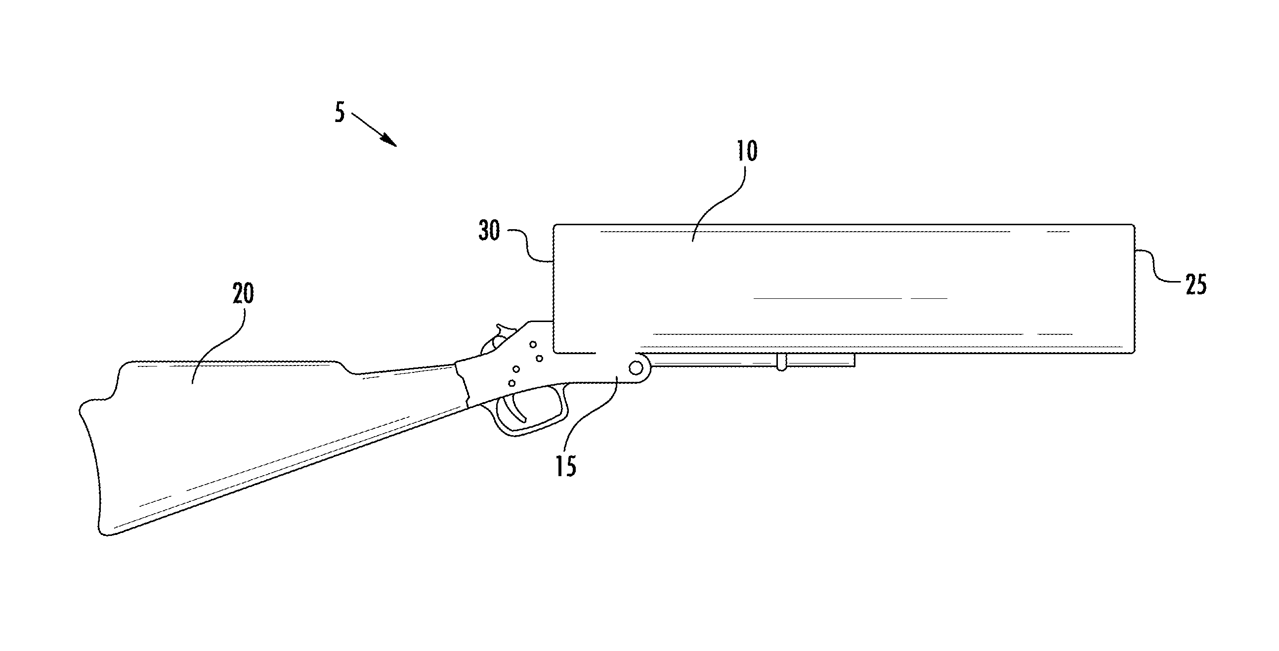
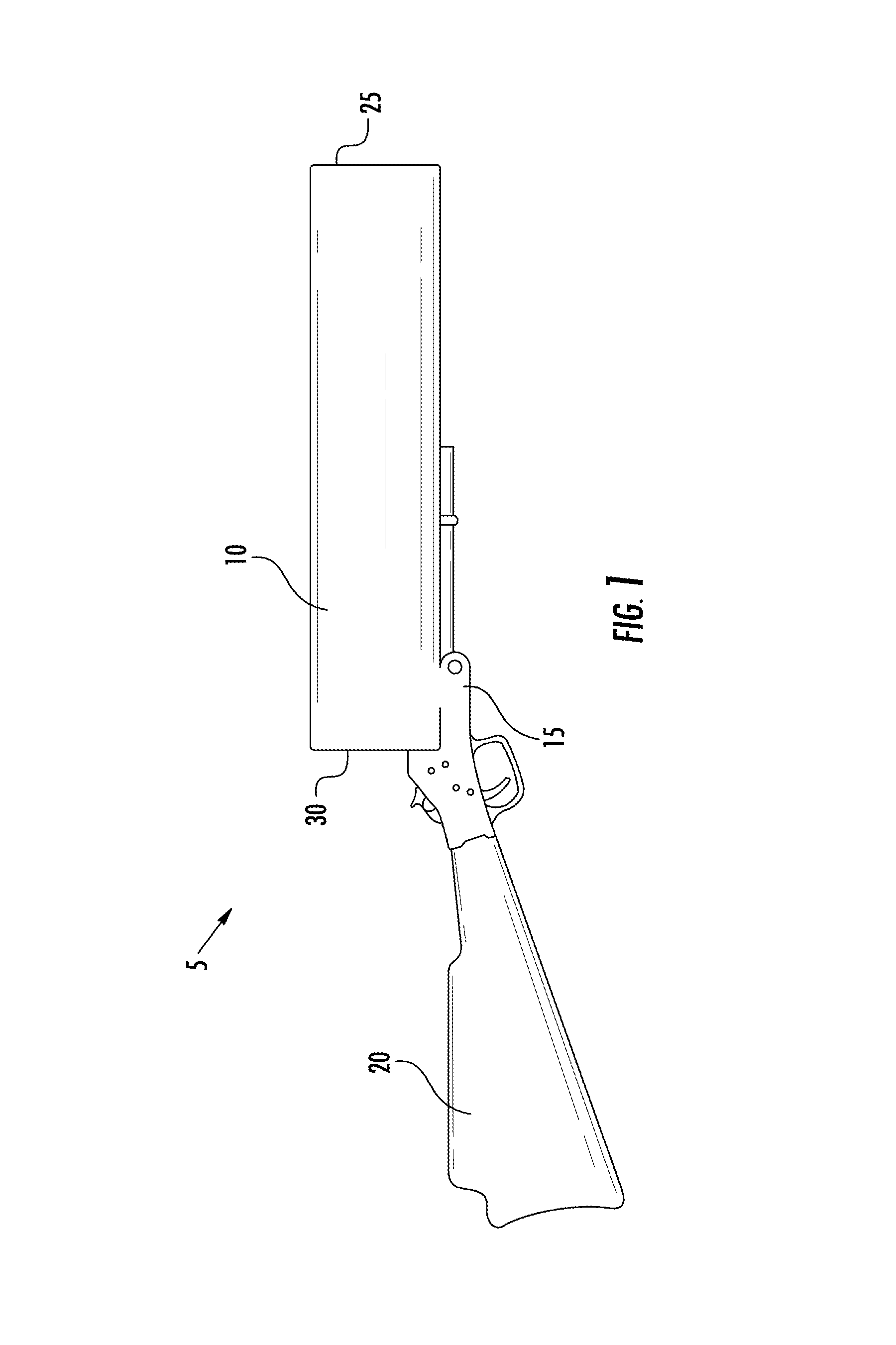
[0038]Aspects of this disclosure relate to launchers and launcher systems for discharging or deploying payloads such as chemical payloads to downrange targets, including those at relatively long ranges (for example, 50 yards and beyond). Moreover, this disclosure provides methods of mitigating or reducing felt recoil that use simple physical principles and that allow the deployment of large payloads with a launcher that can be handheld or shoulder mounted. Reference in this disclosure of a “shoulder mounted” launcher is merely illustrative and unless the context suggests otherwise, does not require the launcher to include a stock with a butt for shoulder mounting.

[0039]The versatility of the disclosed method and the launchers are exemplified in the types of payloads that can be launched with the disclosed system, which include chemical, powder, gel, fire suppression, pyrotechnic, marker, tracer, signaling, non-lethal projectile, frangible, anti-personnel, explosive, smoke, incendiar...


PUM


Abstract

This disclosure relates to launchers and launcher systems for discharging or launching payloads to downrange targets, and associated methods of using such launcher systems. This disclosure further provides methods for attenuating or reducing felt recoil such that relatively large weight payloads can be launched while the launcher is handheld or mounted in any manner. Examples of payloads that can be deployed with the disclosed launcher apparatus include chemical, biological, pyrotechnic, marker, tracer, signaling, non-lethal, anti-personnel, explosive, smoke, and similar payloads.

Description

CROSS REFERENCE TO RELATED APPLICATIONS[0001]This application claims the benefit of U.S. Provisional Application No. 61 / 515,099, filed Aug. 4, 2011, the disclosure of which is incorporated herein by reference in its entirety.TECHNICAL FIELD OF THE INVENTION[0002]This disclosure relates to systems for discharging payloads, including chemical payloads, to downrange targets.BACKGROUND OF THE INVENTION[0003]Cartridge systems that contain a particular payload to be launched constitute extremely practical constructions for deploying almost any material or projectile downrange. Typical cartridge systems incorporate the desired payload, a propellant, and some priming composition all within a self-contained unit. While ammunition cartridges are prototypical of cartridge devices, useful cartridge systems have been designed to launch other payloads, such as chemical, pyrotechnic, marker, tracer, signaling, non-lethal projectiles, explosive, smoke, and other payloads such as anti-personnel, to ...

Claims


Application Information

Patent Timeline
Patent Type & Authority Patents(United States)
IPC IPC(8): F41G5/06F41A1/02F41A1/08
CPCF41A1/02F41A1/08F41A19/14
Inventor MENEFEE, III, JAMES, Y.
Owner POLYWAD
Learn More