Gas circulation structure of equipment front end module (EFEM)

a technology of gas circulation and equipment, which is applied in the direction of chemistry apparatus and processes, dispersed particle separation, separation processes, etc., can solve the problems of difficult service and maintenance, large amount of time for initial gas filling, and complex structure, so as to shorten the time required for gas filling, enhance circulation efficiency, and reduce noise

Pending Publication Date: 2022-09-29
RORZE TECH
View PDF3 Cites 0 Cited by
  • Summary
  • Abstract
  • Description
  • Claims
  • Application Information

AI Technical Summary

Benefits of technology

[0011]With the above structure, in attempt to use the present invention, a user first pumps gas through the gas inlet port into the connection pipeline to allow the gas to be blown, by means of the structural arrangement of the first fan, into the filter assembly to be subject to filtration to then enter the chamber. Afterwards, the second fan of the wind collection device blows the gas inside the chamber back into the connection pipeline to achieve an effect of circulation by means of the first fan again so that the gas is repeatedly flowing in the equipment front end module. To discharge or evacuate the gas, the gas discharge valve is operated to allow the gas inside the connection pipeline to flow out through the gas outlet port and, further, new gas is introduced through the gas inlet port to thereby achieve the purpose of replacing the gas in the interior.
[0012]The equipment front end module according to the present invention is used to keep and preserve a wafer, and by means of the structure and operation described above, the environment in which the wafer is kept can keep circulating and flowing of the gas, and also shortening the time required for filling the gas, and the wind collection device can be used to make gas flow converging to thereby enhance the circulation efficiency, reduce noise, and also to properly blow away dusts and achieve an effect of easing service and maintenance.

Problems solved by technology

However, the following drawbacks exist for a known EFEM during replacement of gas and further improvement is required.
Firstly, the machine itself and a chamber thereof are bulky in size so that it takes a large amount of time for initial filling of gas.
Secondly, the structure is complicated and this makes service and maintenance difficult.
Thirdly, the pipeline in a converging form that is available in the market often leads to generation of noise during blowing and feeding gas.
Fourthly, the pipeline in a converging form that is available in the market would make dust scattering all around if the speed at which gas is blown is excessively large and the dust may not be blown away if the blowing speed if excessively slow.

Method used


Image

  • Gas circulation structure of equipment front end module (EFEM)
  • Gas circulation structure of equipment front end module (EFEM)
  • Gas circulation structure of equipment front end module (EFEM)

Examples


Embodiment Construction

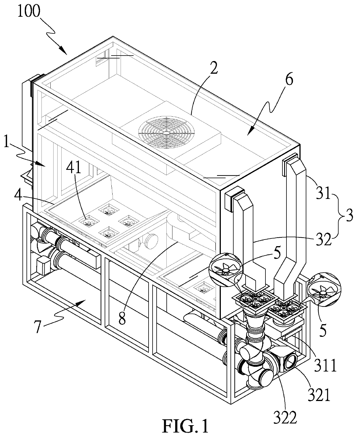
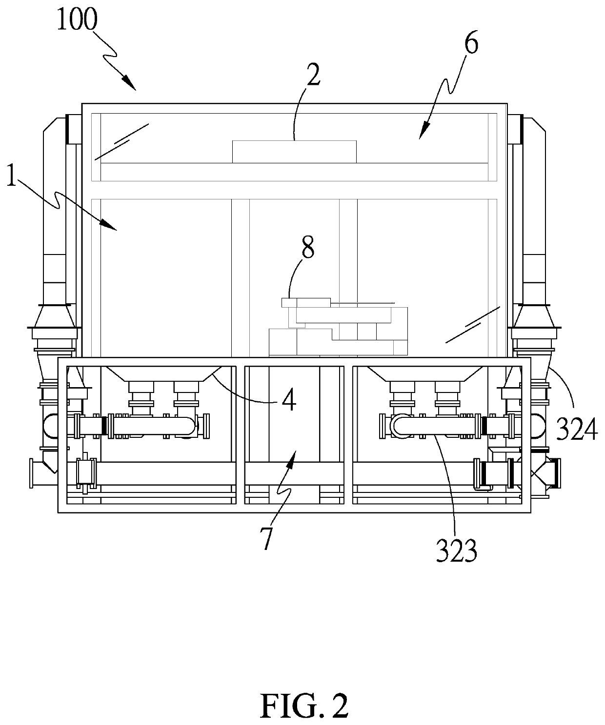
[0024]Referring to FIGS. 1 and 2, which are respectively a perspective view, in a see-through form, showing a first preferred embodiment of the present invention and a front view of the first preferred embodiment of the present invention, it can be clearly seen from the drawings that the present invention comprises:

[0025]a chamber 1;

[0026]a filter assembly 2, the filter assembly 2 being arranged at one side of the chamber 1 and in communication with the chamber 1;

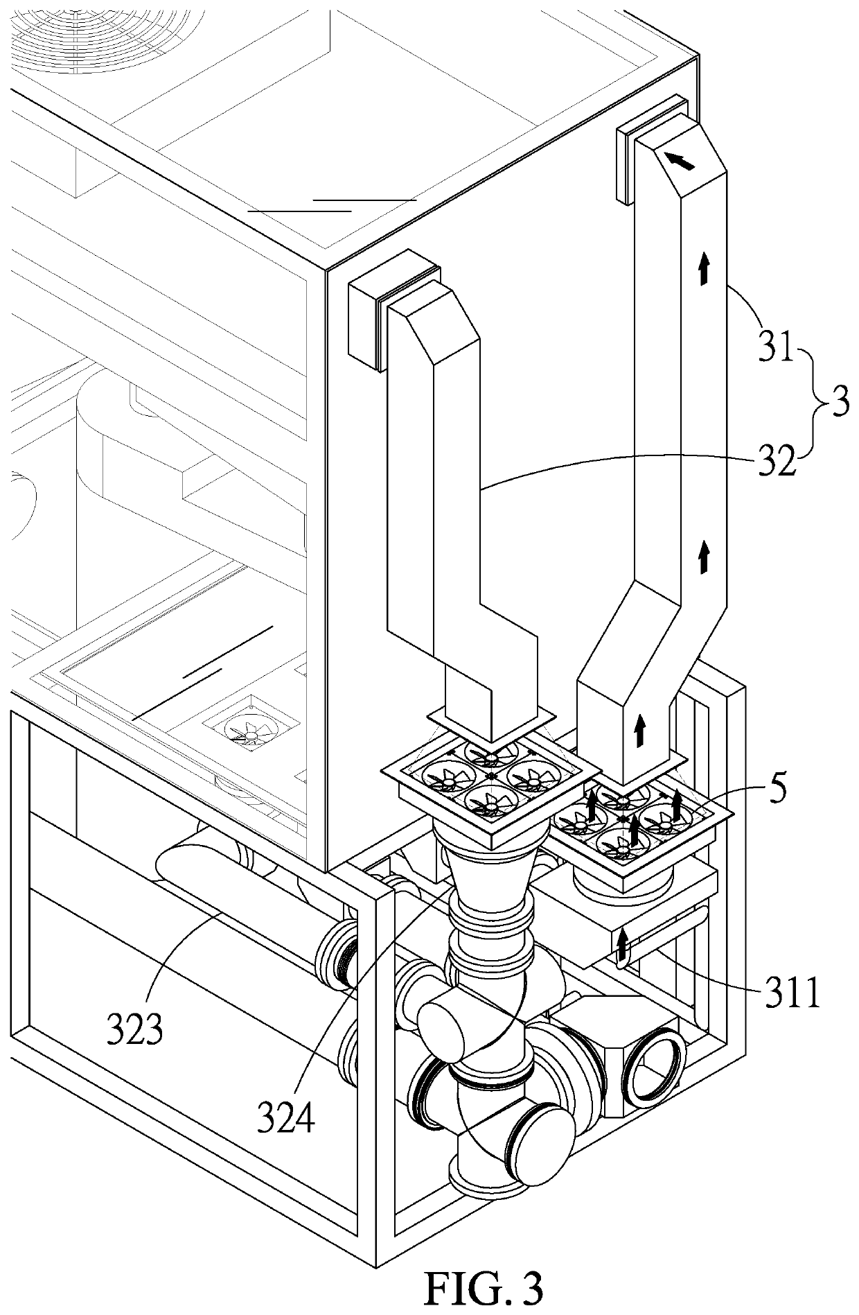
[0027]at least one connection pipeline 3, the connection pipeline 3 having an end in communication with the chamber 1 and an opposite end connected to the filter assembly 2 to convey gas from the chamber 1 into the filter assembly 2, the connection pipeline 3 having a pipeline width that is gradually diverging in a direction from the chamber 1 toward the filter assembly 2;

[0028]at least one wind collection device 4, the wind collection device 4 being arranged at a connection site between the connection pipeline 3 and the ch...


PUM

PropertyMeasurementUnit
widthaaaaaaaaaa
sizeaaaaaaaaaa
speedaaaaaaaaaa

Abstract

A gas circulation structure of an equipment front end module is provided, having a main structure including a chamber, a filter assembly, at least one connection pipeline, at least one wind collection device, at least one first fan, at least one second fan, at least one gas inlet port, at least one gas outlet port, and at least one gas discharge valve. By means of the above structure, gas is introduced through the gas inlet port into the connection pipeline and passes through the first fan to move, through the filter module, into the chamber to be caused by the second fan to return back to the connection pipeline to complete circulation. As such, the time required for filling gas is shortened; gas is caused to converge to thereby enhance the circulation efficiency; noise is reduced; dust is properly blown away; and subsequent service and maintenance is made easy.

Description

TECHNICAL FIELD OF THE INVENTION[0001]The present invention relates to a gas circulation structure of an equipment front end module, and more particularly to a gas circulation structure of an equipment front end module that shortens the time required for filling gas, converges a gas flow to enhance a circulation efficiency, reduces noise, properly blows away dusts, and is easy to service and maintain.DESCRIPTION OF THE PRIOR ART[0002]In the field of semiconductor, to prevent a wafer from being contaminated, an environment of transportation for the wafer must be subject to severe control and management. Firstly, a front opening unified pod (FOUP) is provided to receive and hold the wafer. A transportation device is operated to transport the wafer that is received in the FOUP to an equipment front end module (EFEM) or a wafer sorter in an environment-controlled condition. Generally, a clean gas is constantly introduced to cause gas circulation in an interior of the EFEM in order to ke...

Claims


Application Information

Patent Timeline
Patent Type & Authority Applications(United States)
IPC IPC(8): H01L21/67B01D46/00
CPCH01L21/67017B01D46/0041B01D2279/51H01L21/67766
Inventor CHANG, JEN-WEILU, CHUNG-HSIENLU, CHENG-HSIANG
Owner RORZE TECH
Why Eureka
Try Eureka