

Foamable filling device
- Summary
- Abstract
- Description
- Claims
- Application Information
AI Technical Summary
Benefits of technology
Problems solved by technology
Method used
Image

Examples
first embodiment
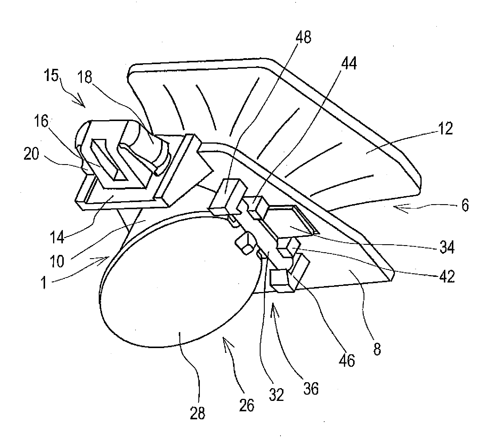
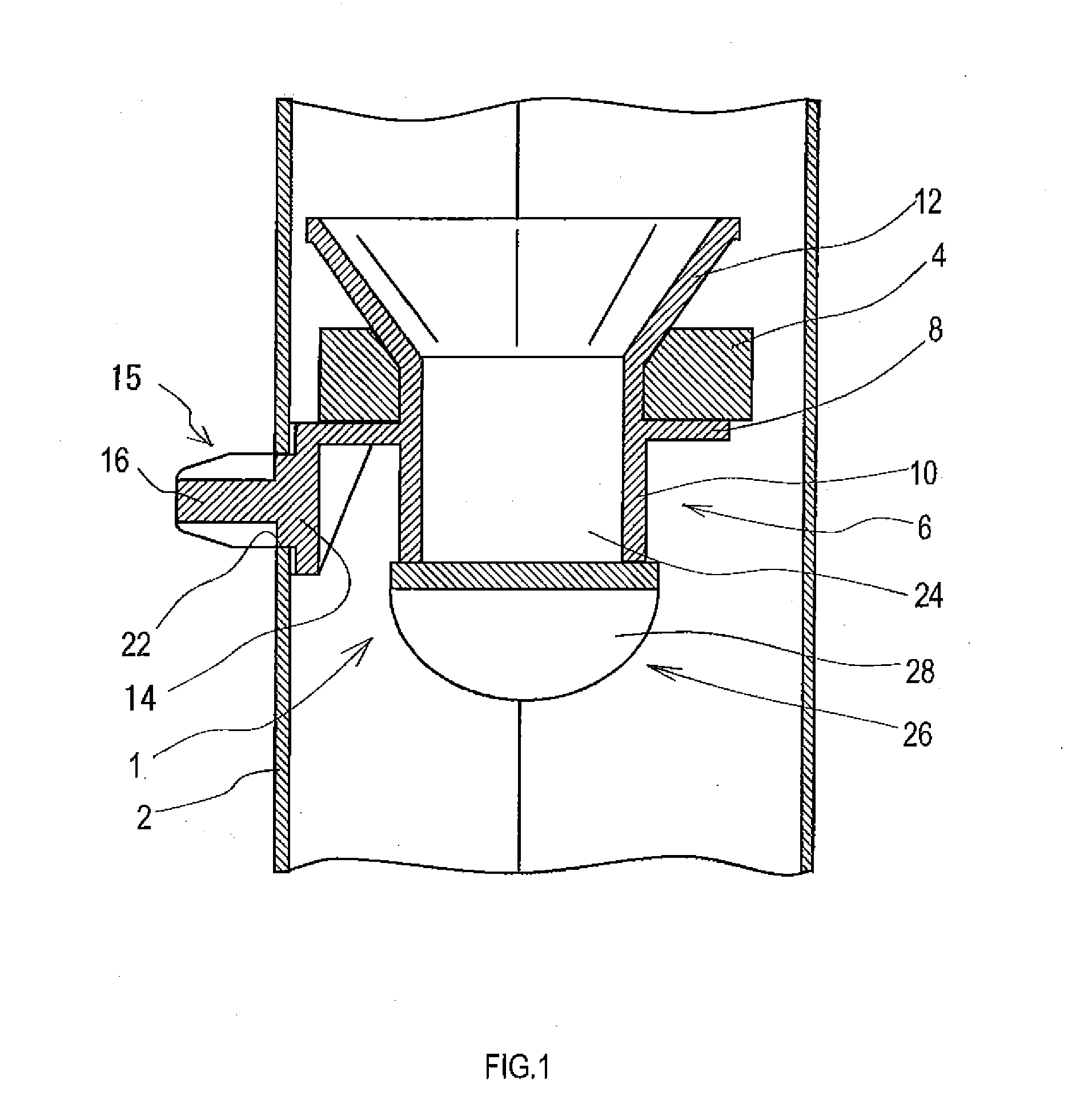
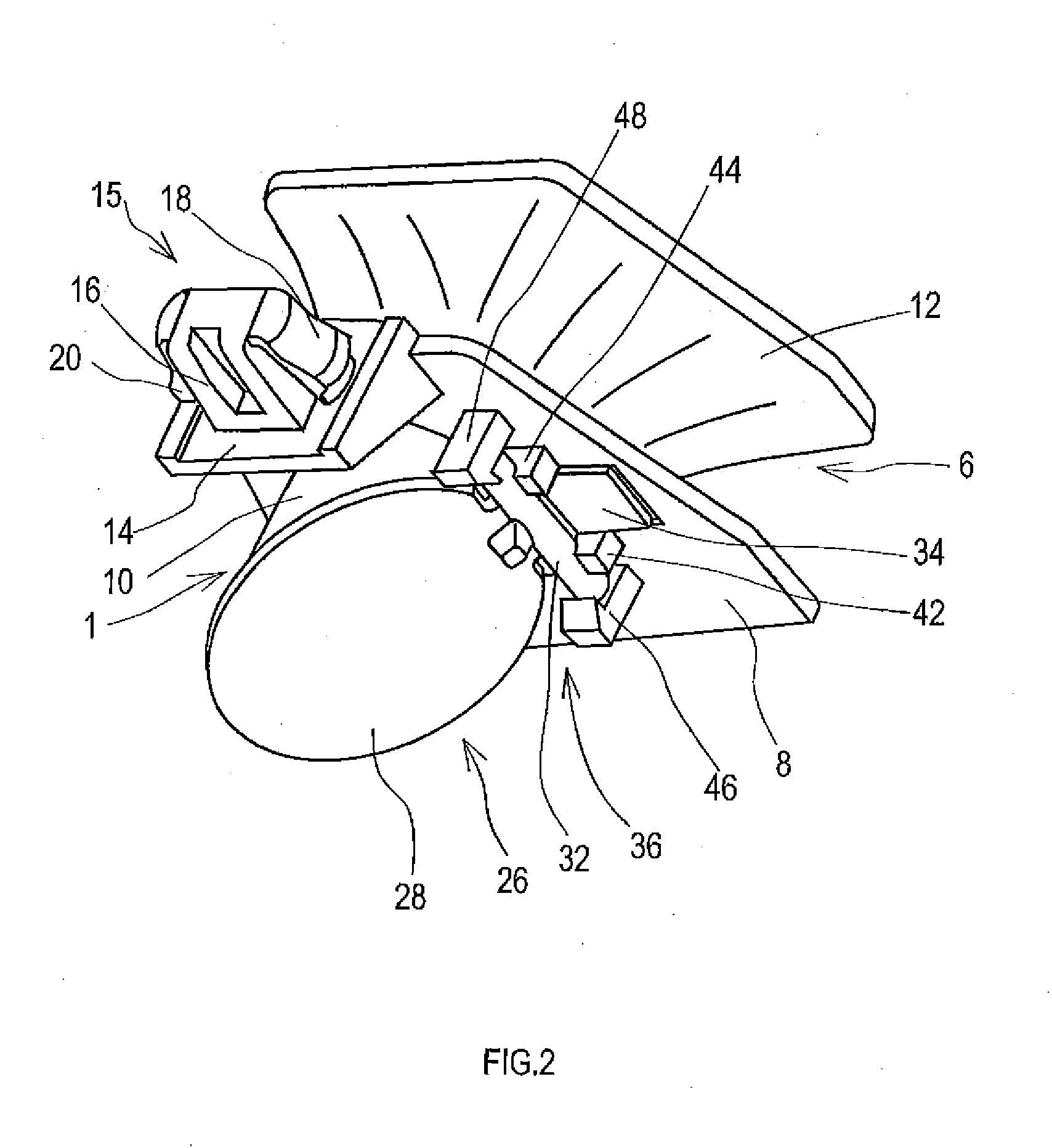
[0045]In this first embodiment, a through hole 24 is formed by the cylindrical portion 10, and at other end of the cylindrical portion 10 (an end on an opposite side of the tapered portion 12), an opening / closing member 26 is provided. The opening / closing member 26 includes a cover portion 28 having a size that blocks the through hole 24. As shown in FIG. 2 and FIG. 3, the other end of the cylindrical portion 10 is formed, as a whole, diagonally to an axial direction of the cylindrical portion 10. Hereinafter, an entire end face of the other end of the cylindrical portion 10 is referred to as a seat portion 30. The cover portion 28 can block the through hole 24 more completely by contacting the seat portion 30 of the cylindrical portion 10.
[0046]As shown in FIG. 5, the opening / closing member 26 includes a fitting portion 32 of a columnar shaft shape. The fitting portion 32 is formed integrally with the cover portion 28 at a part of an outer edge of the cover portion 28. An axial dir...
fourth embodiment
[0065]An engagement portion 74 of the fourth embodiment includes a pair of pillar portions 76a, 76b provided to stand on the flat plate portion 8 so as to be able to be positioned on both sides of the fitting portion 32a. Between the pillar portions 76a, 76b, a shaft portion 78 of a columnar shape is put across. The shaft portion 78 passes through the slit 72 and is engaged with the fitting portion 32a of a cylindrical shape, and the fitting portion 32a is thereby rotatably supported by the engagement portion 74.
[0066]Similarly to the foamable filling device 1 of the first embodiment, in the above-described foamable filling devices 51, 61, 71 of the second to fourth embodiments, too, even when the coating material as a process liquid flows in, the cover portion 28 is spaced apart from the seat portion 30 by the fluid pressure of the coating material against the biasing force of the biasing portion 34, and the coating material passes through the seat portion 30 (the outlet of the thr...
sixth embodiment
[0079]The engagement portion 108 of the sixth embodiment is configured as an engagement hole penetratingly formed in the flat plate portion 8b. By inserting the fitting portion 106 into the engagement portion 108, the engagement portion 108 and the fitting portion 106 are engaged with each other, and one end (a leading end) of the biasing portion 104 is fixed to the flat plate portion 8b. At the same time, the biasing portion 104 on a side of the cover portion 28 is elastically deformed, and the cover portion 28 is biased by a biasing force generated as a result of such elastic deformation such that the cover portion 28 comes into contact with the seat portion 30.
[0080]Similarly to the foamable filling device 1 of the first embodiment, in the case of the foamable filling device 101 of the sixth embodiment, too, even when the coating material flows into the hollow structural member 2 to which the foamable filling device 101 is mounted, the cover portion 28 is spaced apart from the se...
PUM
| Property | Measurement | Unit |
|---|---|---|
| Force | aaaaa | aaaaa |
| Shape | aaaaa | aaaaa |
Abstract
Description
Claims
Application Information