Eureka AIR delivers breakthrough ideas for toughest innovation challenges, trusted by R&D personnel around the world.

Image forming apparatus

Active Publication Date: 2014-01-02
COPYER
View PDF0 Cites 3 Cited by
  • Summary
  • Abstract
  • Description
  • Claims
  • Application Information

AI Technical Summary

Benefits of technology

The present invention prevents the flap of an envelope from sticking to the main body of the envelope. This is achieved by designing a conveying surface for one rotary member in a pair of rotary members that nips and conveys the flap, in a way that separates from the surface of the other rotary member, so as not to nip the adhesion portion of the flap.

Problems solved by technology

When the envelope is heated by the fixing device, the moisture in the envelope often evaporates.
Therefore, when the envelope is heated by the fixing device, the moisture of the envelope may evaporate, and the adhesive applied to the flap may dissolve by the evaporated moisture.
Therefore, the flap releasing mechanism often peels off the flap after the flap is stuck to the envelope main body, and thus the envelope is damaged in some cases.

Method used


Image

  • Image forming apparatus
  • Image forming apparatus
  • Image forming apparatus

Examples


Embodiment Construction

[0029]In the following, an image forming apparatus according to each embodiment of the present invention is described with reference to the drawings. The numerical values in the embodiments are reference numerical values, and are not numerical values that limit the present invention.

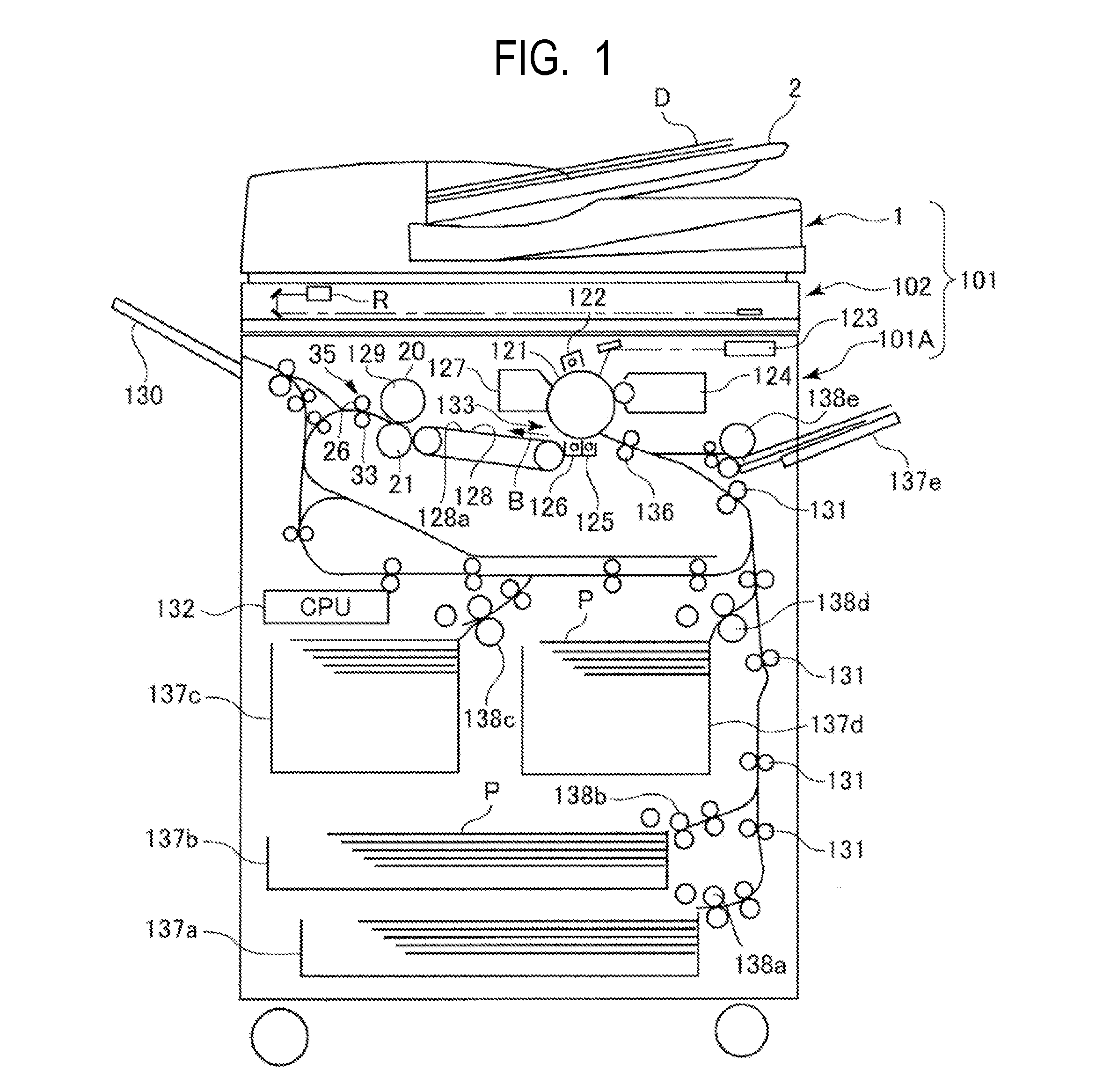
[0030]FIG. 1 is a sectional view of an image forming apparatus according to an embodiment of the present invention.

[0031]An image forming apparatus 101 includes an apparatus main body 101A, an image reader 102 provided on an upper portion of the apparatus main body, and an original feeder 1 provided on the image reader 102.

[0032]The original feeder 1 automatically conveys an original D placed on an original feeding tray 2 by a user to the image reader 102. The image reader 102 receives, at an image reading position R, light radiated to and reflected on the original that is conveyed inside the original feeder 1, optically reads the original for conversion into an electrical signal, and creates image data ...


PUM


Abstract

To prevent a flap of an envelope to stick to an envelope main body, provided is an image forming apparatus including: an image forming portion forming a toner image on the envelope; a fixing device fixing the toner image onto the envelope by heating the envelope while conveying the envelope on which the toner image is formed by the image forming portion; and a conveying roller pair that rotates while nipping the envelope, onto which the toner image is fixed by the fixing device, to convey the envelope. A driven roller of the conveying roller pair includes driven runners divided in a rotary shaft center direction, and one driven runner located at one end is inclined in a direction separating from another driven runner so that an outer peripheral surface of the one driven runner is brought into contact with a corner portion of a rubber roller.

Description

BACKGROUND OF THE INVENTION[0001]1. Field of the Invention[0002]The present invention relates to an image forming apparatus which is configured to fix a toner image on an envelope.[0003]2. Description of the Related Art[0004]Hitherto, an image forming apparatus employing an electrophotographic system, such as a copying machine and a printer, has been configured to fix a toner image on an envelope, onto which the toner image is formed by an image forming portion, by conveying and heating the envelope with use of a fixing device. After that, in the image forming apparatus, the envelope is nipped by a pair of rotary members, and is conveyed by the rotation thereof. When the envelope is heated by the fixing device, the moisture in the envelope often evaporates.[0005]A water-soluble adhesive is often applied to the flap (flap part) of the envelope. Therefore, when the envelope is heated by the fixing device, the moisture of the envelope may evaporate, and the adhesive applied to the flap...

Claims


Application Information

Patent Timeline
IPC IPC(8): G03G15/20
CPCG03G15/2085G03G2215/00514G03G15/6594G03G15/2028G03G15/6573
Inventor OHNISHI, TAKAHIRO
Owner COPYER
Why Eureka
Eureka Blog
Learn More