Eureka AIR delivers breakthrough ideas for toughest innovation challenges, trusted by R&D personnel around the world.

Check valve

Active Publication Date: 2016-02-11
ZAMA JAPAN
View PDF2 Cites 2 Cited by
  • Summary
  • Abstract
  • Description
  • Claims
  • Application Information

AI Technical Summary

Benefits of technology

The present invention allows for a more reliable check valve to be provided in a simple structure. By preventing the valve body from sticking and ensuring stability when holding the valve body, the valve body can move vertically while remaining parallel to the valve seat, resulting in an improved effect compared to conventional techniques. The support member (retainer) is formed from the same material and process as used conventionally, and includes a flat protruding top portion as the contact location with the valve body, ensuring planar contact.

Problems solved by technology

Therefore, there is a large difference in the check valves described in Patent Application Nos.

Method used


Image

  • Check valve
  • Check valve
  • Check valve

Examples


Embodiment Construction

[0031]Next, a preferred embodiment of the present invention will be described with reference to drawings.

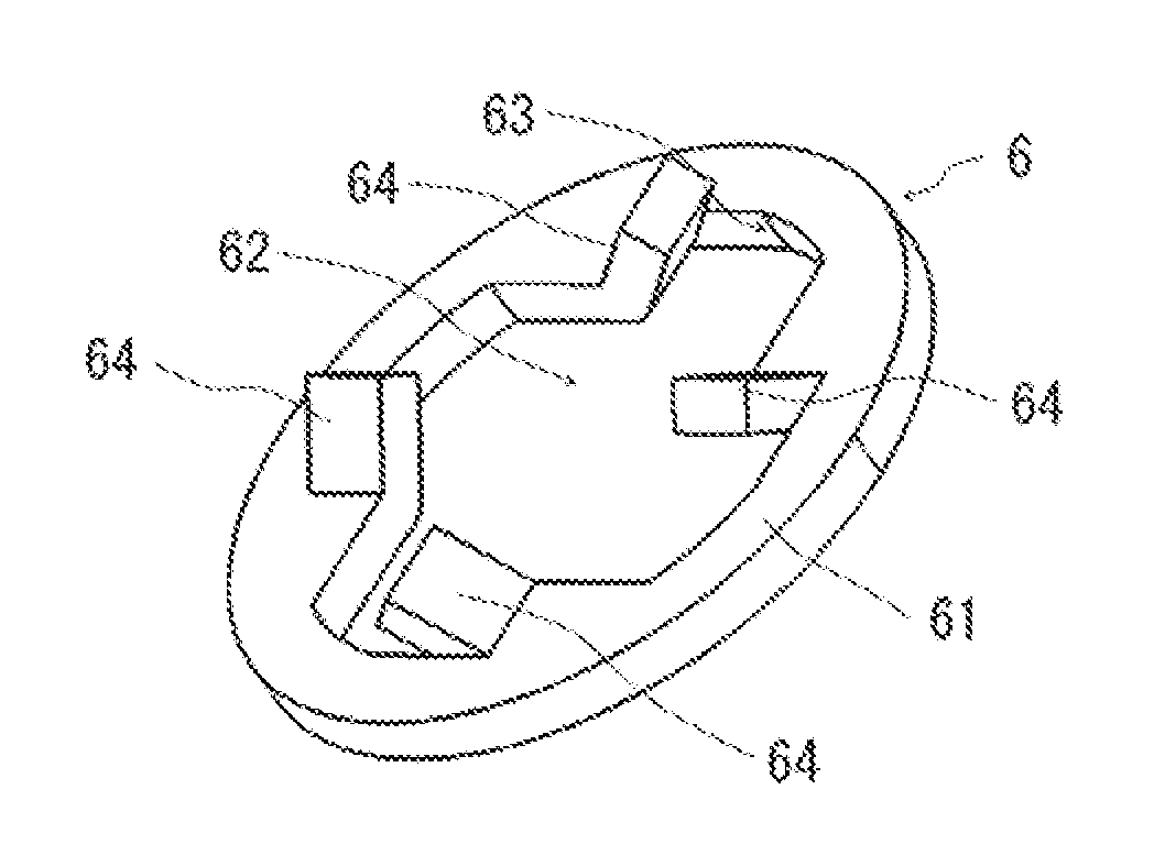
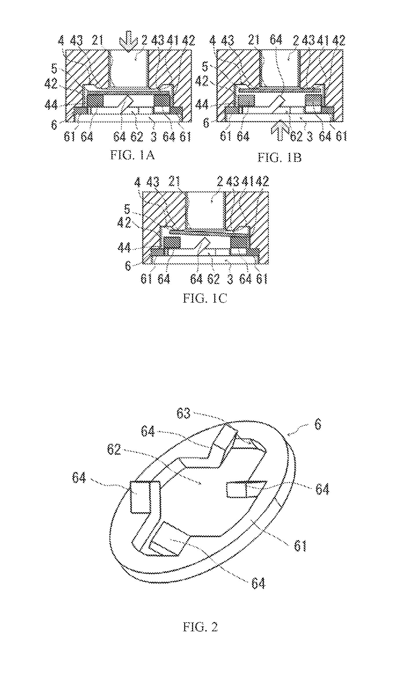
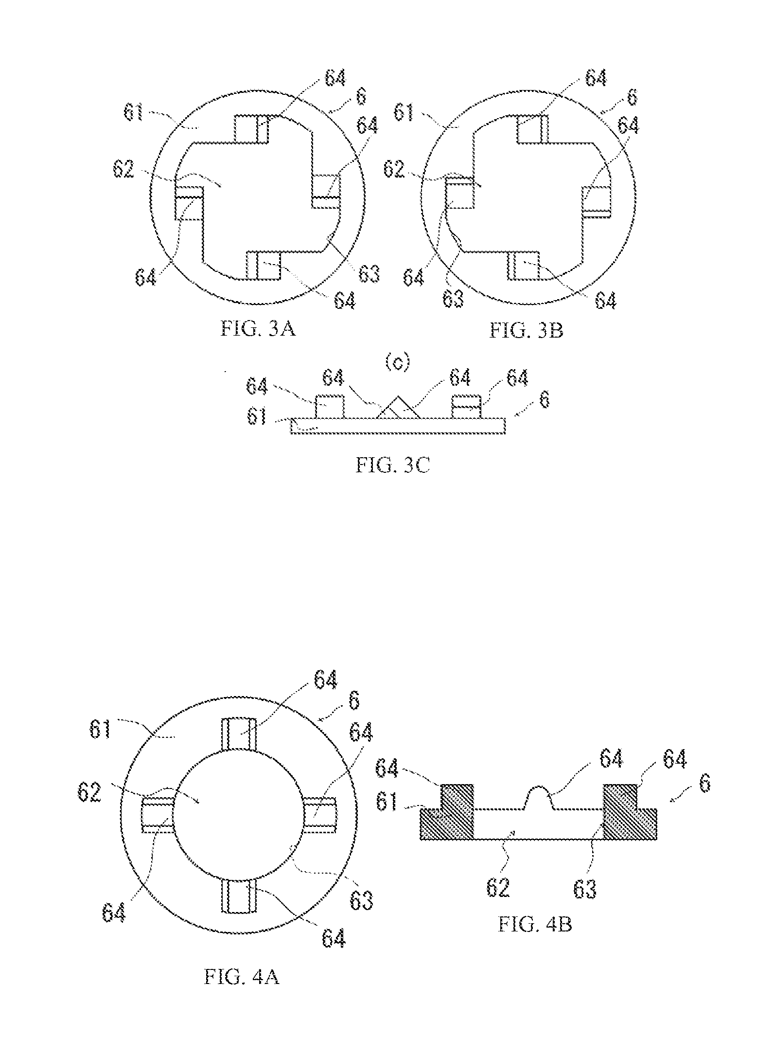
[0032]FIGS. 1A, 1B and 1C illustrate vertical cross-sectional views of a preferred embodiment of a check valve which is the present invention. The overall configuration is substantially similar to that of the conventional technique shown in FIGS. 6A, 6B and 6C and is configured in that an inflow opening 2 and an outflow opening 3 are formed in a cylindrical shape on both ends, respectively, and include: a case body 1 made of, for example, an aluminum die cast forming a cylindrically shaped valve seat 4 having a predetermined length in an axial direction between the inflow opening 2 and the outflow opening 3; a disk shaped valve body 5 having an outer diameter slightly smaller than the inner diameter of the valve seat 4 and disposed with the ability to move in an axial direction of the valve seat 4 by a larger diameter than the inner diameter of the inflow opening 2; and a support...


PUM


Abstract

A check valve that can prevent sticking of a valve body and reliably perform an opening and closing action in a check vale having a simple structure and that does not use biasing means on the valve body. A check valve has support pieces of a valve body protruding in the valve body direction on a circular base seat forming an outflow window in the center inserted in a circular groove where a support member (retainer) is formed between an outflow opening and a valve seat and on an open edge of the outflow window formed in the center of the base seat, and the support pieces of the support member (retainer) that support the valve body have linear or planar support parts on the top portion for leveling at least in a radial direction of the base seat.

Description

TECHNICAL FIELD[0001]The present invention relates to a check valve used in a fuel passage of a carburetor for the purpose of, for example, preventing reverse flow of fuel.BACKGROUND TECHNOLOGY[0002]Check valves that allow fluid to flow out in only one direction and prevent the reverse flow have been known in the past, and various types such as a ball type, swing type, lift type, and disk type according to the structure of a valve have been known. A purpose of the check valve is to prevent the reverse flow of fluid, and since overall the body is not complicated, such as the disk type, it can be provided at a low cost, is easily installed in the middle of a tubular body, and therefore it is suitable for disposing, for example, in a fuel passage of a carburetor or the like.[0003]Further, a disk type check valve forms an inflow opening and an outflow opening by a casing as described in, for example, Japanese Unexamined Patent Application Nos. H10-288265 and H07-101066, and a ring-shape...

Claims


Application Information

Patent Timeline
IPC IPC(8): F16K15/02F02M17/14F16K27/02
CPCF16K15/02F02M17/145F16K27/0209F02M17/32F16K15/023
Inventor SASAKI, HIDEKI
Owner ZAMA JAPAN
Why Eureka
Eureka Blog
Learn More