Eureka AIR delivers breakthrough ideas for toughest innovation challenges, trusted by R&D personnel around the world.

Thermal printhead

Active Publication Date: 2010-11-18
ROHM CO LTD
View PDF3 Cites 6 Cited by
  • Summary
  • Abstract
  • Description
  • Claims
  • Application Information

AI Technical Summary

Benefits of technology

[0008]The present invention has been proposed under the circumstances described above. It is, therefore, an object of the present invention to provide a thermal printhead which is capable of preventing sticking while maintaining proper printing speed.
[0010]With the above-described arrangement, the overall heat transfer coefficient of the protective film is adjusted as desired by appropriately setting the thickness of the high thermal conductivity portion and the low thermal conductivity portion. Thus, the degree of temperature rise and temperature drop of a recording medium such as thermal paper can be adjusted properly, so that the sticking is prevented while the printing speed is maintained.
[0013]Preferably, the thermal conductivity of the protective film becomes lower as proceeding away from the heating resistor in the thickness direction of the protective film.

Problems solved by technology

Sticking (the phenomenon in which a recording medium sticks to a printhead) is a conventionally known problem which often occurs in a thermal printhead.
However, the rapid temperature change of the thermal paper is not suitable for preventing the sticking.

Method used


Image

  • Thermal printhead
  • Thermal printhead
  • Thermal printhead

Examples


Embodiment Construction

[0020]Preferred embodiments of the present invention will be described below with reference to the accompanying drawings.

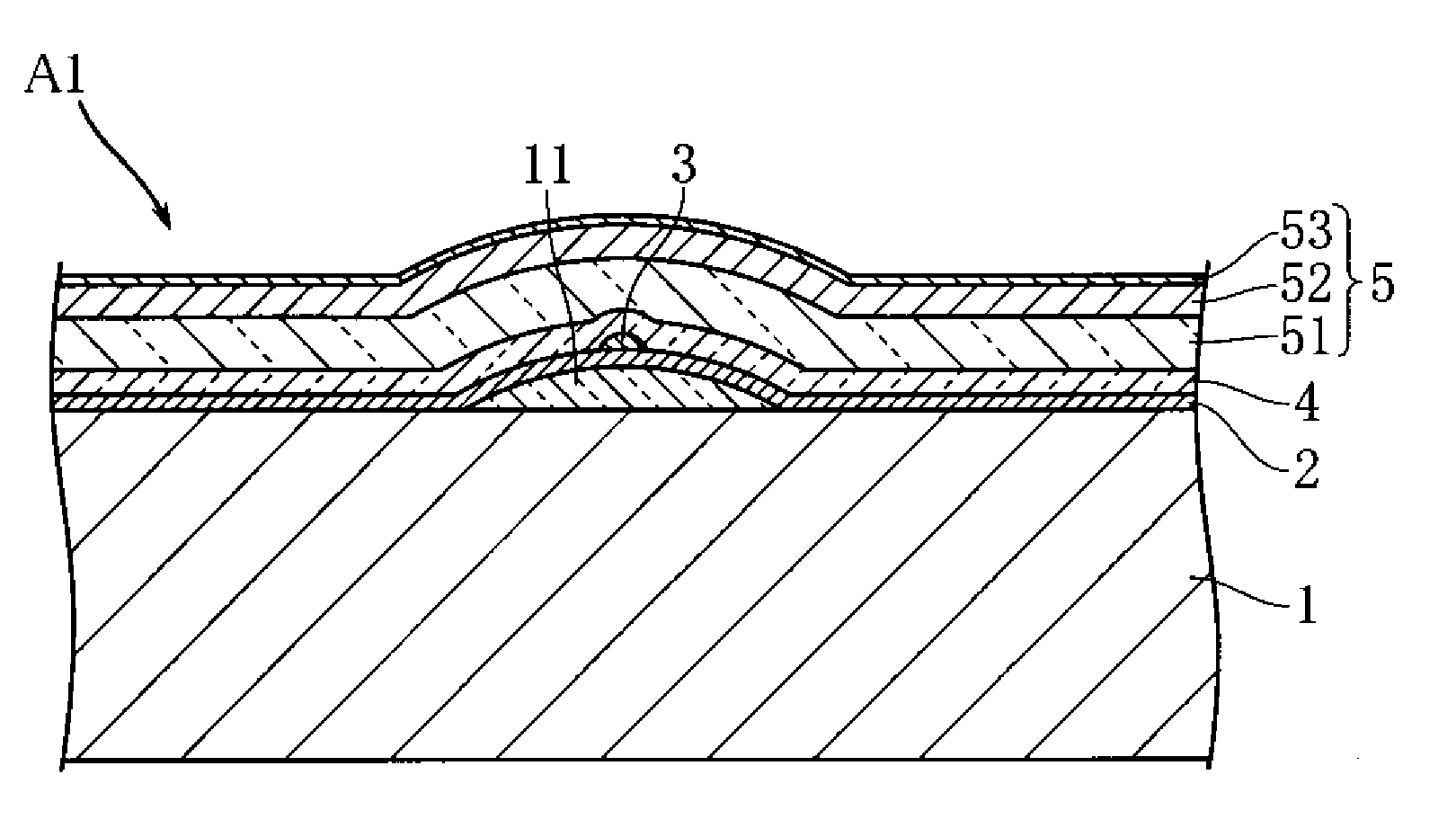
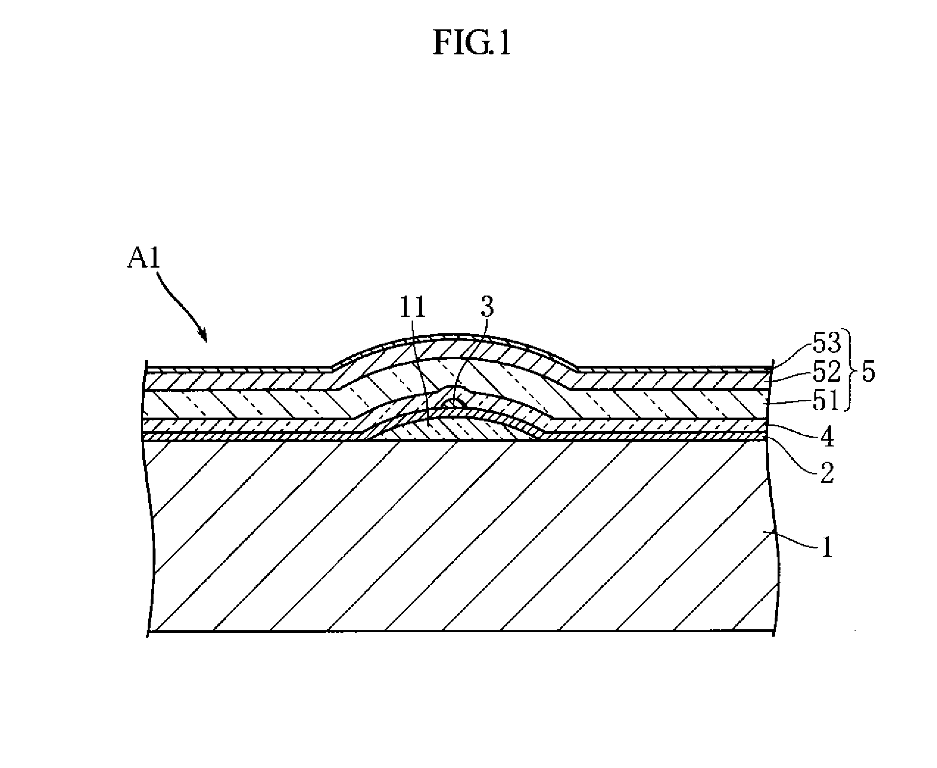
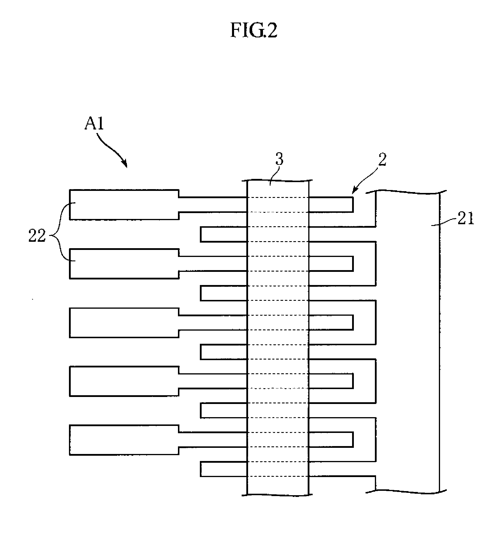
[0021]FIGS. 1 and 2 show a thermal printhead according to a first embodiment of the present invention. The illustrated thermal printhead A1 includes a substrate 1, an electrode pattern 2, a heating resistor 3, a glass layer 4 and a protective film 5. It is to be noted that only the electrode pattern 2 and the heating resistor 3 are shown in FIG. 2.

[0022]The substrate 1 comprises an insulating substrate which is rectangular in plan view and elongated in the primary scanning direction. The substrate is made of e.g. alumina ceramic material. A partial glaze 11 is formed on the upper surface of the substrate 1. The partial glaze 11 is in the form of a strip extending in the primary scanning direction. As will be understood from the sectional view of FIG. 1, the partial glaze 11 bulges in the thickness direction of the substrate 1.

[0023]The electrode pattern 2 is provi...


PUM


Abstract

A thermal printhead (A1) includes a substrate (1) and a heating resistor (3) supported by the substrate (1). An electrode pattern (2) is formed in contact with the heating resistor (3) for applying driving voltage. The heating resistor (3) is covered with a protective film (5). The protective film (5) includes a high thermal conductivity layer (51) and a low thermal conductivity layer (52) laminated on the high thermal conductivity layer. The low thermal conductivity layer (52) is positioned farther from the heating resistor (3) than the high thermal conductivity layer (51) is.

Description

TECHNICAL FIELD[0001]The present invention relates to a thermal printhead incorporated in a thermal printer.BACKGROUND ART[0002]A thermal printhead includes an insulating substrate and a heating resistor formed on the substrate. In printing, current is applied to the heating resistor, whereby images or letters are formed on a recording medium such as thermal paper (see Patent Document 1 below).[0003]FIG. 5 is a partial sectional view showing an example of conventional thermal printhead. The thermal printhead X shown in the figure includes a substrate 91 and a partial glaze 92 elongated in the primary scanning direction. A plurality of electrodes 93 extending in the secondary scanning direction are provided on the substrate 91. A heating resistor 94 extending across the electrodes 93 (i.e., in the primary scanning direction) is provided on the partial glaze 92. A protective film 95 for protecting the heating resistor 94 and other parts is provided on the substrate 91. In printing, th...

Claims


Application Information

Patent Timeline
IPC IPC(8): B41J2/335
CPCB41J2/3351B41J2/33515B41J2/3357B41J2/3353B41J2/33525
Inventor YAMADE, TAKUMI
Owner ROHM CO LTD
Why Eureka
Eureka Blog
Learn More