Eureka AIR delivers breakthrough ideas for toughest innovation challenges, trusted by R&D personnel around the world.

Thermal printhead

Active Publication Date: 2009-07-09
ROHM CO LTD
View PDF5 Cites 5 Cited by
  • Summary
  • Abstract
  • Description
  • Claims
  • Application Information

AI Technical Summary

Benefits of technology

[0006]The present invention has been proposed under the circumstances described above. It is, therefore, an object of the present invention is to provide a thermal printhead which is capable of preventing sticking.

Problems solved by technology

Conventionally, however, the thermal paper having a smooth surface tends to stick to the protective film 94 when pressed against the thermal printhead X. When such a phenomenon (called “sticking”) occurs, the thermal paper cannot be smoothly slid relative to the thermal printhead X, which may result in deterioration in printing quality.
Moreover, the above-described coating agent is generally hydrophilic and tends to absorb moisture in the air.

Method used


Image

  • Thermal printhead
  • Thermal printhead
  • Thermal printhead

Examples


first embodiment

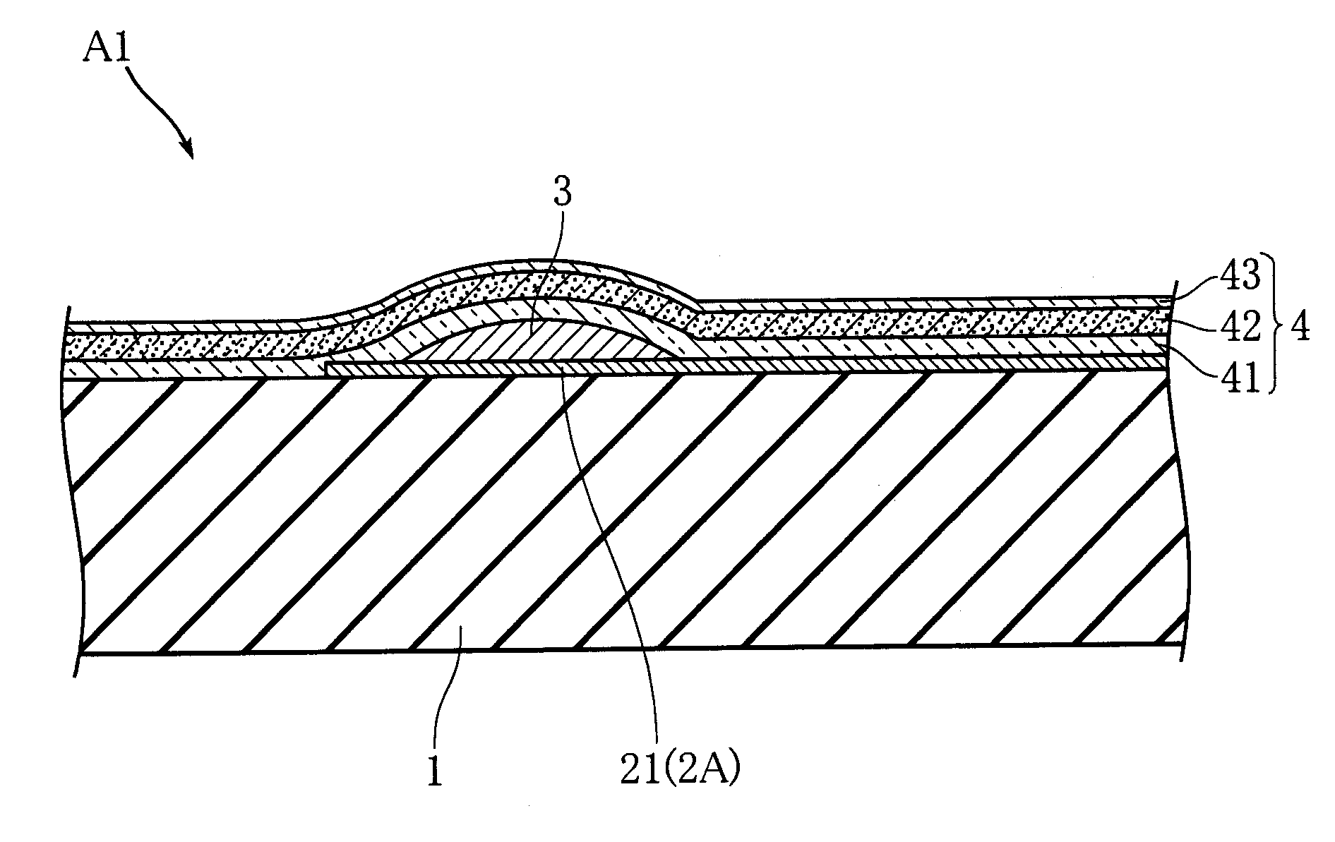
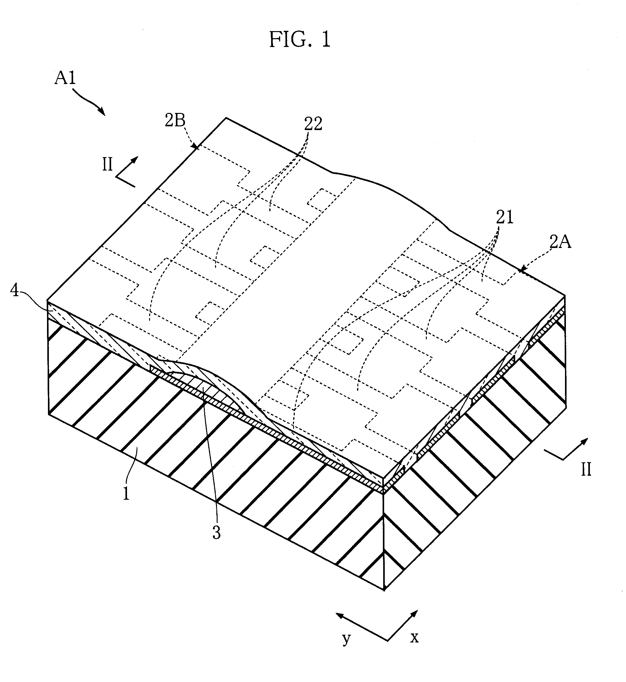
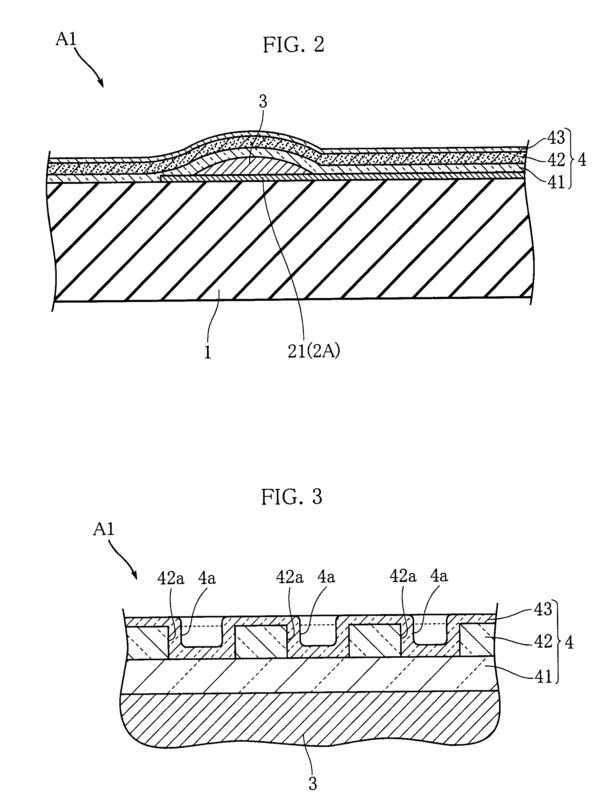
[0022]FIGS. 1-3 show a thermal printhead according to the present invention. The illustrated thermal printhead A1 includes an insulating substrate 1, electrodes 2A and 2B, a heating resistor element 3 and a protective film 4. The heating resistor element 3 is elongated in the primary scanning direction (x direction in FIG. 1). In printing, recording paper such as thermal paper is transferred in the secondary scanning direction (y direction in FIG. 1) relative to the thermal printhead A1.

[0023]The substrate 1 is made of e.g. a ceramic material. A glaze layer (not shown) is formed on the substrate 1 to provide a smooth surface. The glaze layer also functions to prevent heat from escaping from the heating resistor element 3 to the substrate 1.

[0024]The electrodes 2A and 2B are made of a metal such as Au and have different electrical polarities. The electrode 2A includes a plurality of comb-teeth-shaped extensions 21 extending in the secondary scanning direction y, and the electrode 2B ...

second embodiment

[0033]As shown in FIGS. 4 and 5, the thermal printhead A2 includes an insulating substrate 1, electrodes 2A and 2B, a heating resistor element 3 and a protective film 4. The substrate 1 is made of e.g. a ceramic material. A non-illustrated glaze layer is formed on the substrate 1. The electrodes 2A and 2B are made of e.g. Au and include a plurality of extensions 21 and 22 extending in the secondary scanning direction y. The extensions 21 and 22 are alternately arranged in the primary scanning direction x. The heating resistor element 3 is made of e.g. ruthenium oxide. The protective film 4 protects the electrodes 2A, 2B and the heating resistor element 3 and has a laminated structure made up of a first layer 41, a second layer 44 and a third layer 45. The first layer 41 is a dense layer directly covering the electrodes 2A, 2B and the heating resistor element 3 and made of e.g. glass. The first layer 41 has a thickness of e.g. about 4 μm. The second layer 44 is made of SiC or a comp...


PUM


Abstract

A thermal printhead (A1) includes an insulating substrate and a heating resistor element (3) formed on the substrate and elongated in the primary scanning direction. A plurality of electrodes are connected to the heating resistor element (3). The electrodes and the heating resistor element (3) are covered by a protective film (4). The protective film (4) includes a first layer (41), a second layer (42) and a third layer (43). The second layer (42) is porous and includes a plurality of pores (42a). The third layer (43) partially enters each of the pores (42a) so that the upper surface pf the protective film (4) is an irregular surface including a plurality or recesses (4a).

Description

TECHNICAL FIELD[0001]The present invention relates to a thermal printhead used for printing on e.g. thermal paper.BACKGROUND ART[0002]FIG. 7 shows an example of conventional thermal printhead (see Patent Document 1 given below). The illustrated thermal printhead X includes a substrate 91 and a heating resistor element 93 extending on the substrate in the primary scanning direction. The heating resistor element 93 is covered by a protective film 94. The heading resistor element 93 is connected to an electrode 92 and another electrode (not shown) whose polarity is opposite to that of the electrode 92. When current is applied to the heating resistor element 93 via these electrodes, heat is generated. The heat is transferred to thermal paper through the protective film 94, whereby an image or letter is formed on the thermal paper.[0003]Patent Document 1: JP-A-7-186429[0004]Generally, to enable clear printing, the surface of thermal paper is made smooth. Examples of such surfacing techni...

Claims


Application Information

Patent Timeline
IPC IPC(8): B41J2/335
CPCB41J2/3357B41J2/3353
Inventor SAKO, TERUHISAKANEI, NAOFUMI
Owner ROHM CO LTD
Why Eureka
Eureka Blog
Learn More