Tire balance measuring device
- Summary
- Abstract
- Description
- Claims
- Application Information
AI Technical Summary
Benefits of technology
Problems solved by technology
Method used
Image

Examples
first embodiment
(Structure of Tire Balance Measuring Device)
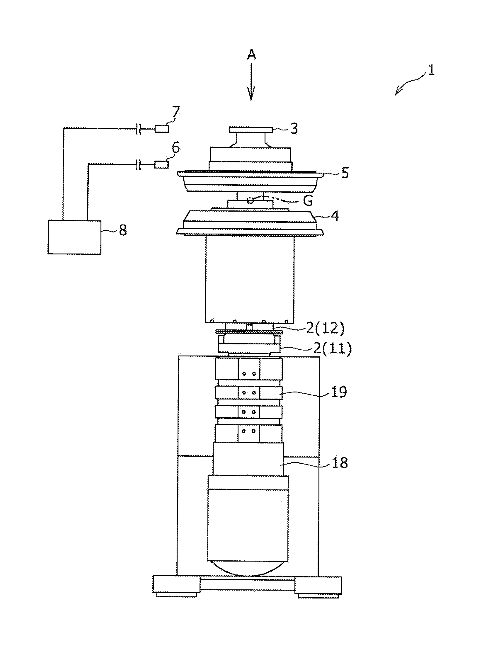
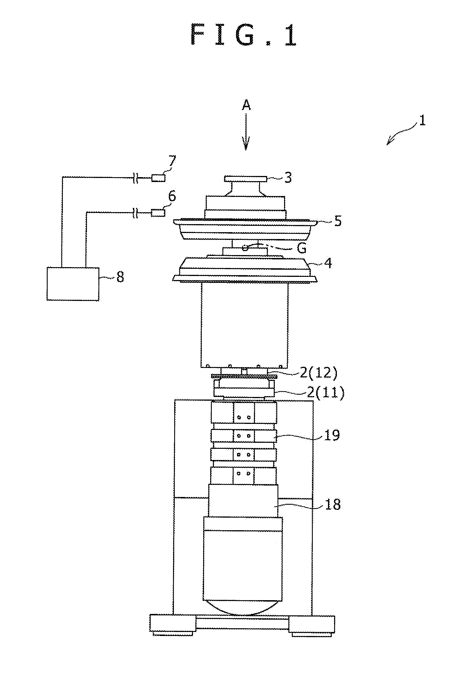
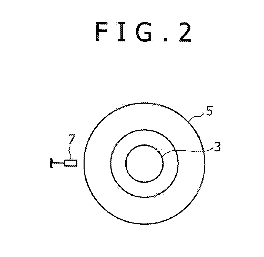
[0020]FIGS. 1 to 3 show a first embodiment of a tire balance measuring device. A tire balance measuring device 1 is designed to hold a tire inserted between an annular lower rim 4 and an annular upper rim 5, and rotate the tire about a vertical axis after air is introduced into the tire to thereby inflate the tire.
[0021]The tire balance measuring device 1 includes a spindle 2 having a top end on which the lower rim 4 is mounted, and a lock shaft 3 having a top end on which the upper rim 5 is mounted. The spindle 2 and the lock shaft 3 respectively correspond to a rim rotation supporting shaft and a locking shaft of the present invention. When the lock shaft 3 whose top end is equipped with the upper rim 5 is inserted into a fitting hole 12a of the spindle 2, the tire can be retained between the lower rim 4 and the upper rim 5 in a condition sandwiched therebetween.
[0022]After the insertion of the lock shaft 3 into the fitting hole 12a in t...
second embodiment
[0056]FIGS. 4 and 5 show the second embodiment. The second embodiment differs in the number and placement of the sensors from the first embodiment, and other components are identical to those of the first embodiment. The same components as those of the first embodiment are designated by the same reference numerals as those of the first embodiment.
[0057]A tire balance measuring device 102 according to the second embodiment includes three sensors 6, 10, and 13.
[0058]The placement of the first sensor 6 is identical to that of the first embodiment. Specifically, the first sensor 6 is the sensor used for detecting the radial position (displacement) of the upper rim 5 and installed in the vicinity of the upper rim 5.
[0059]The second sensor 10 is a sensor used for detecting an axial position (displacement) of the upper rim 5. The second sensor 10 is arranged at an angle substantially the same as that of the first sensor 6 in the rotational direction of the upper rim 5. In this embodiment, ...
PUM
 Abstract
Description
Claims
Application Information
PatSnap Eureka turns technology decisions into work you can execute. Powered by our Innovation Knowledge Graph, it runs expert workflows across engineering, life sciences, materials and intellectual property. Get your review-ready output in minutes.


