Electric Vehicle Driven with Interaction with Rider

a technology of electric vehicles and rider, applied in the field of electric vehicles, can solve the problems of inclination of the body, inconvenient holding and lifting the operating shaft, and a little or serious injury to the rider, and achieve the effect of convenient performan

Inactive Publication Date: 2014-01-09
ROBO3
View PDF0 Cites 80 Cited by
  • Summary
  • Abstract
  • Description
  • Claims
  • Application Information

AI Technical Summary

Benefits of technology

[0011]It is another object of the present invention to provide an electric vehicle driven with the interaction with a rider wherein a foot board is located in such a manner as to be isolated downwardly by a given dist...

Problems solved by technology

However, it is really hard for a beginner to incline his body forward due to his anxiety about falling down and to incline his body backward so as to reduce the speed of the forward riding, and during his practice, he may be a little or seriously injured.
During riding, besides, if any of the two wheels 60 is broken and does not work, the...

Method used


Image

  • Electric Vehicle Driven with Interaction with Rider
  • Electric Vehicle Driven with Interaction with Rider
  • Electric Vehicle Driven with Interaction with Rider

Examples


first embodiment

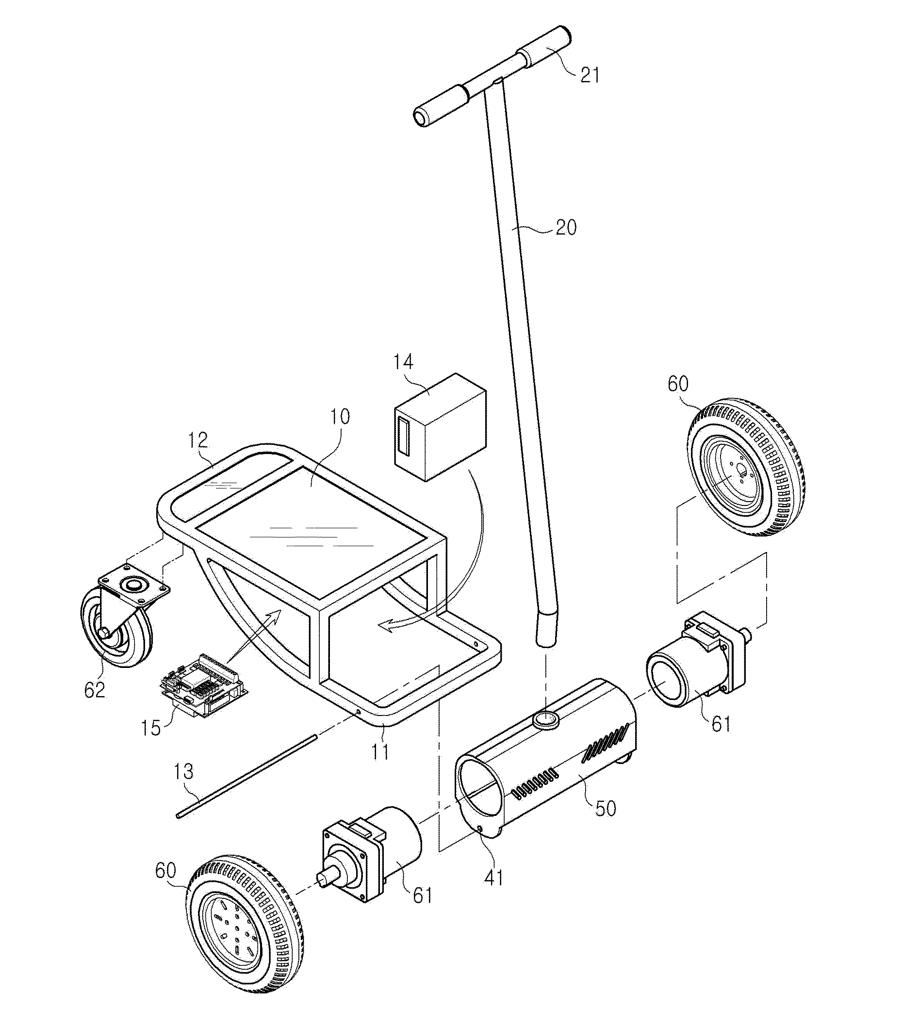
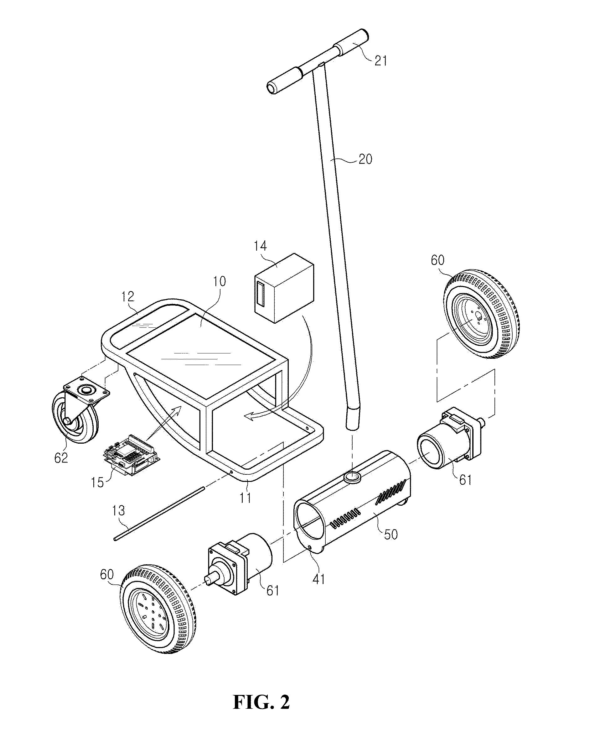
[0031]FIG. 2 is a separate perspective view showing an electric vehicle driven with the interaction with a rider according to the present invention, and as shown in FIG. 2, an operating shaft 20 is rigidly inserted fixedly into the center of the upper portion of a motor housing 50, and steering handles 21 are mounted correspondingly on the left and right sides of the front end of the operating shaft 20 to change the drive direction of the electric vehicle.

[0032]Motors 61 are mounted onto the interiors of both sides of the motor housing 50 to drive wheels 60 coupled thereto, and the wheels 60 are rotatably coupled to the shafts of the motors 61. On the other hand, a foot board 10 is mounted on the rear side of the operating shaft 20, on which a rider stands, and a battery 14 is mounted on the underside of the foot board 10 to supply power to the motors 61. Further, a controller 15 on which various sensors inclusive of a Gyro sensor are mounted is disposed on the underside of the foot...

second embodiment

[0041]FIG. 9 is a front view showing a wheel rotary axis line and a foot board connection shaft line of the electric vehicle according to the present invention, and as shown in FIGS. 7 and 9, a front connection member 11 formed on the front end of the foot board 10 is fitted to foot board shaft holes 41 formed on the second stand 40 by means of a connection shaft 13, and in this case, the front connection member 11 is isolated downwardly by a given distance H from a wheel rotary axis line X as the center of the front wheel 60.

[0042]Accordingly, as shown in FIG. 9, a foot board connection shaft line X′ of the foot board 10 is set lower than the wheel rotary axis line X of the front wheel 60 by means of the front connection member 11, so that the operating shaft 20 in the electric vehicle according to the second embodiment of the present invention can be maintained in an upright state during parking, without falling down on the ground. This principle has been mentioned in the first em...

third embodiment

[0048]FIG. 13 is a front view showing a wheel rotary axis line and a foot board connection shaft line of the electric vehicle according to the present invention, and as shown in FIGS. 11 and 13, a front connection member 11 formed on the front end of the foot board 10 is fitted to foot board shaft holes 41 formed on the second stand 40 by means of a connection shaft 13, and in this case, the front connection member 11 is isolated downwardly by a given distance H from a wheel rotary axis line X as the center of the front wheel 60.

[0049]Accordingly, as shown in FIG. 13, a foot board connection shaft line X′ of the foot board 10 is set lower than the wheel rotary axis line X of the front wheel 63 by means of the front connection member 11, so that the operating shaft 20 in the electric vehicle according to the third embodiment of the present invention can be upright during parking, without falling down on the ground. This principle has been mentioned in the third embodiment of the pres...


PUM


Abstract

An electric vehicle including: an operating shaft inserted into the center of the upper portion of a motor housing and having steering handles mounted on the front end thereof to change the drive direction of the vehicle; motors mounted onto the interiors of both sides of the motor housing and having front wheels coupled correspondingly thereto; a foot board mounted on the rear side of the operating shaft; a battery and a controller mounted on the underside of the foot board; a rear connection member protruded backwardly from the board and having a caster mounted on the underside thereof; and a front connection member protruded forwardly from the foot board, coupled by a connection shaft to foot board shaft holes formed on the lower ends of both sides of the motor housing, in a state of being isolated downwardly.

Description

CROSS-REFERENCE TO RELATED APPLICATION[0001]This application claims the benefit under 35 U.S.C. §119 of Korean Patent Application No. 10-2012-0073779, filed Jul. 6, 2012, which is hereby incorporated by reference in its entirety.BACKGROUND OF THE INVENTION[0002]1. Field of the Invention[0003]The present invention relates to an electric vehicle, and more particularly, to an electric vehicle driven with the interaction with a rider that is capable of performing riding manipulations inclusive of moving forward and backward by pushing an operating shaft taken by the rider in a forward direction to move forward and by pulling the operating shaft in a backward direction to move backward, thereby being driven with the interaction with the rider's arm actions.[0004]2. Background of the Related Art[0005]FIG. 1 is a perspective view showing an upright riding type electric vehicle of the prior art. As shown in FIG. 1, an upright riding type electric vehicle 70 performs riding by in real time m...

Claims


Application Information

Patent Timeline
IPC IPC(8): B62D51/02B62D61/08B62D61/02B62D61/06
CPCB62K2204/00B62K11/007B60L50/66Y02T10/70B62K11/02B62K11/14B62K17/00B62K23/02B62M7/00B62M7/12Y02T10/64
Inventor KIM, JOON HYUNGKANG, TAE HO
Owner ROBO3
Why Eureka
Try Eureka