Symmetric Magnet Arrangement for Medical Implants

a magnet arrangement and medical implant technology, applied in the field of permanent magnet arrangement, can solve the problems of not being strong enough to hold the external transmitter housing in the proper position, damage to adjacent tissue in the patient, magnetic resonance imaging,

Active Publication Date: 2014-01-09
MED EL ELEKTROMEDIZINISCHE GERAETE GMBH
View PDF7 Cites 54 Cited by
  • Summary
  • Abstract
  • Description
  • Claims
  • Application Information

AI Technical Summary

Benefits of technology

[0032]Although various exemplary embodiments of the invention have been disclosed, it should be apparent to those skilled in the art that various changes and modifications can be made which will achieve some of the advantages of the invention without departing from the true scope of the invention.

Problems solved by technology

One problem arises when the patient undergoes Magnetic Resonance Imaging (MRI) examination.
Among other things, this may damage the adjacent tissue in the patient.
In addition, the external magnetic field B from the MRI may reduce or remove the magnetization m of the implant magnet 202 so that it may no longer be strong enough to hold the external transmitter housing in proper position.
The implant magnet 202 may also cause imaging artifacts in the MRI image, there may be induced voltages in the receiving coil, and hearing artifacts due to the interaction of the external magnetic field B of the MRI with the implanted device.
This is especially an issue with MRI field strengths exceeding 1.5 Tesla.
Thus, for existing implant systems with magnet arrangements, it is common to either not permit MRI or at most limit use of MRI to lower field strengths.
But the spherical magnet arrangement requires a relatively large magnet much larger than the thickness of the other components of the implant, thereby increasing the volume occupied by the implant.
This in turn can create its own problems.
This is an additional step during implantation in such applications which can be very challenging or even impossible in case of very young children.
However, there is no suggestion that such therapeutic arrangements might potentially have any utility for magnetic attachment applications such as those described above.

Method used


Image

  • Symmetric Magnet Arrangement for Medical Implants
  • Symmetric Magnet Arrangement for Medical Implants
  • Symmetric Magnet Arrangement for Medical Implants

Examples


Embodiment Construction

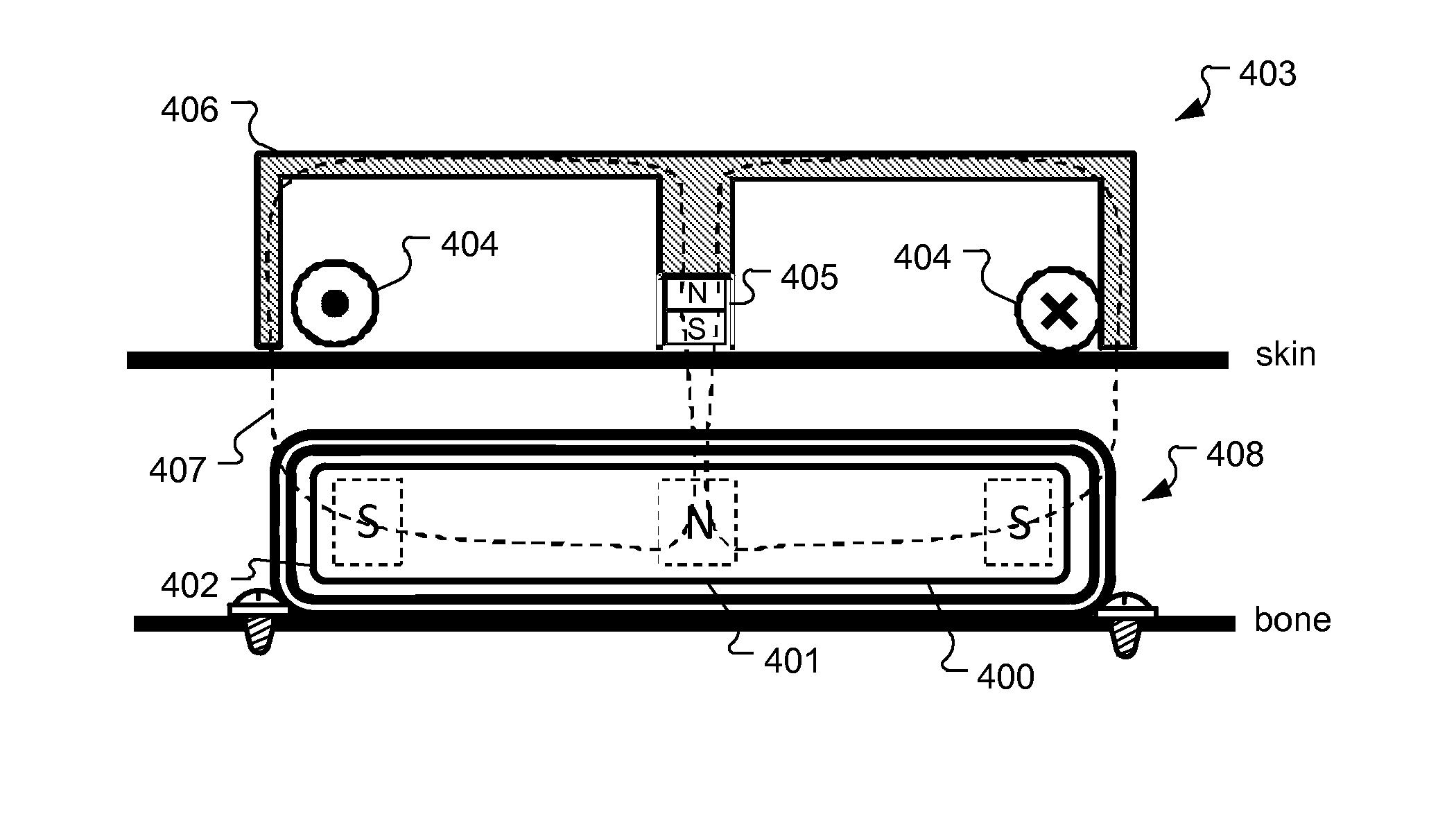
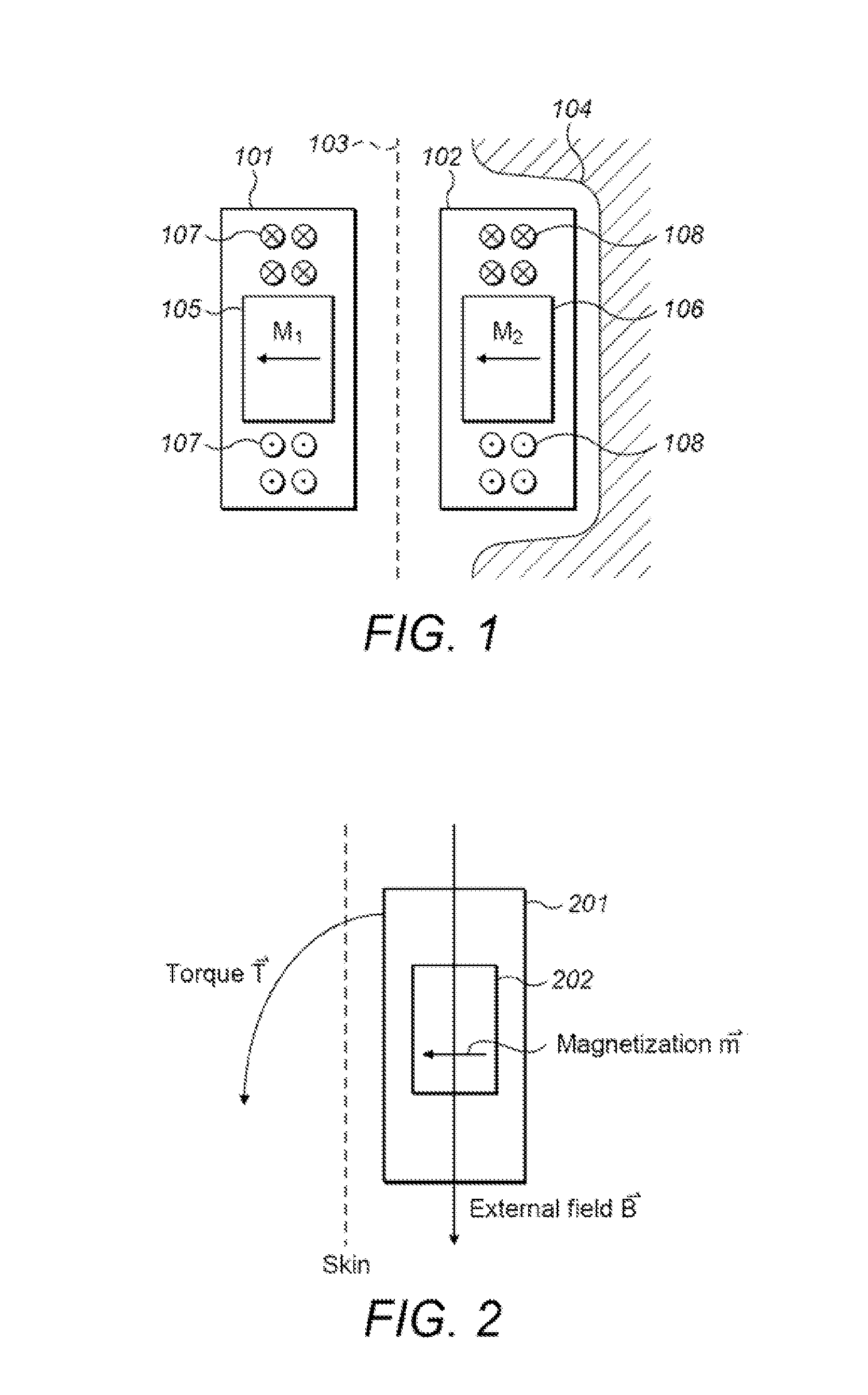
[0022]Various embodiments of the present invention are directed to a two-fold symmetric implant magnet arrangement (e.g., radially symmetric) for a medical implant system including without limitation hearing implants (cochlear implant, middle ear implant, bone conduction implant, or vestibular implant), visual implants and laryngeal pacemakers. The magnet arrangement produces a low torque in the presence of an external homogenous magnetic field such as for an MRI examination, yet the near field magnetic force (for magnetic interaction with a corresponding external holding magnet) is high enough to be comparable to that produced by a conventional cylindrical magnet. Such magnet arrangements can be useful both for functioning as a holding magnet component to hold an external unit in a desired position on the skin of the patient user, and also for functioning as an actuator magnet in a mechanical stimulation implant such as a bone conduction implant.

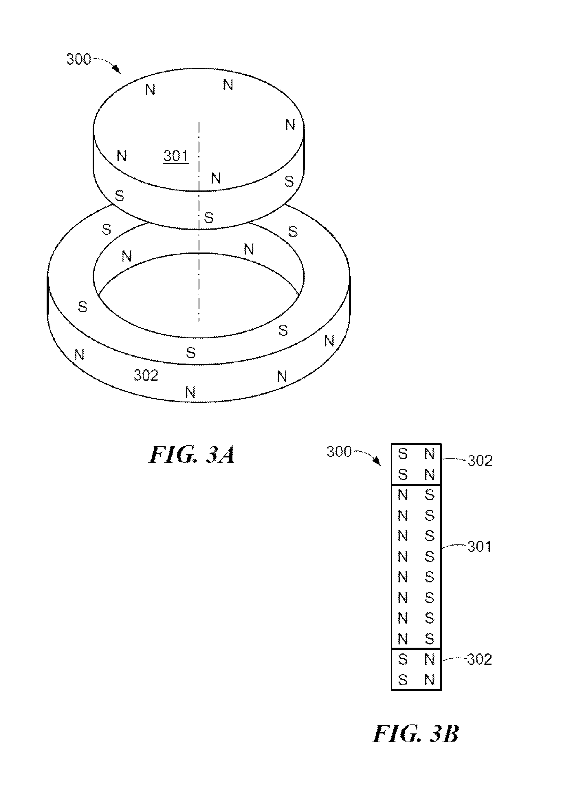
[0023]FIG. 3A shows an exploded elev...


PUM


Abstract

An arrangement is described for a hearing implant system. An implantable housing has an outer surface configured to lie under and parallel to the skin of the implanted patient. An implant magnet arrangement is located within the implantable housing and has multiple local magnetic sections with different independent local magnetic fields that are combined together to form a net magnetic field with at least two-fold symmetry and zero net magnetic dipole moment, wherein the magnetic fields are oriented parallel to the outer surface of the implant housing.

Description

[0001]This application claims priority from U.S. Provisional Patent Application 61 / 669,161, filed Jul. 9, 2012, which is incorporated herein by reference in its entirety.FIELD OF THE INVENTION[0002]The present invention relates to medical implants, and more specifically to a permanent magnet arrangement for use in such implants.BACKGROUND ART[0003]Some hearing implants such as Middle Ear Implants (MEI's) and Cochlear Implants (CI's) employ attachment magnets in the implantable part and an external part to hold the external part magnetically in place over the implant. For example, as shown in FIG. 1, a typical cochlear implant system may include an external transmitter housing 101 containing transmitting coils 107 and an external magnet 105. The external magnet 105 has a conventional coin-shape and a north-south magnetic dipole that is perpendicular to the skin of the patient to produce external magnetic field lines M1 as shown. Implanted under the patient's skin is a corresponding r...

Claims


Application Information

Patent Timeline
Patent Type & Authority Applications(United States)
IPC IPC(8): H04R25/00
CPCH04R25/60A61N1/08A61N1/3718A61N1/375H04R25/606A61N1/36036A61N1/37518H04R11/02
Inventor NAGL, MARKUSLECHLEITNER, THOMASLAMPACHER, PETERAMRHEIN, WOLFGANGWEIDENHOLZER, GUNTHER
Owner MED EL ELEKTROMEDIZINISCHE GERAETE GMBH
Why Eureka
Try Eureka