Robot control apparatus, robot control method, program, and recording medium

a robot control and robot control technology, applied in the field of robot control apparatus, robot control method, program, and recording medium, can solve the problem of difficulty in accurately attaching the grasped object to the other object, and achieve the effect of accurate assembly and assembly

Inactive Publication Date: 2014-01-09
CANON KK
View PDF7 Cites 69 Cited by
  • Summary
  • Abstract
  • Description
  • Claims
  • Application Information

AI Technical Summary

Benefits of technology

[0020]Accordingly, even when the position of the first workpiece grasped by the hand unit is shifted or the first workpiece is deformed, accurate assembly is realized. Furthermore, even when a position of the camera is shifted, accurate assembly is realized.

Problems solved by technology

Here, if the hand unit grasps different positions of the object at different times, it is difficult to accurately attach the grasped object to the other object.

Method used


Image

  • Robot control apparatus, robot control method, program, and recording medium
  • Robot control apparatus, robot control method, program, and recording medium
  • Robot control apparatus, robot control method, program, and recording medium

Examples


first embodiment

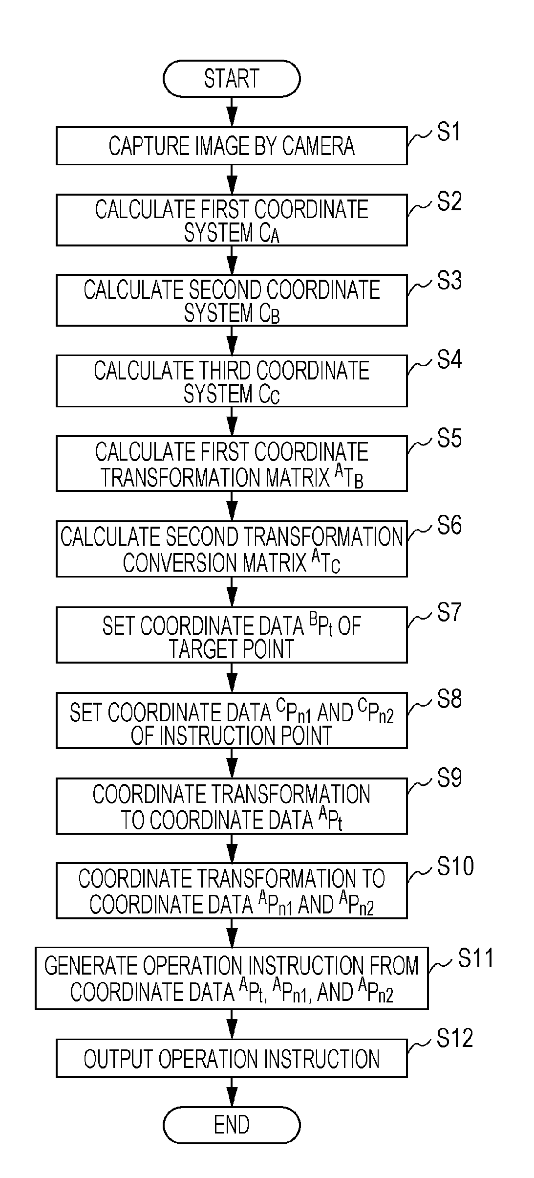
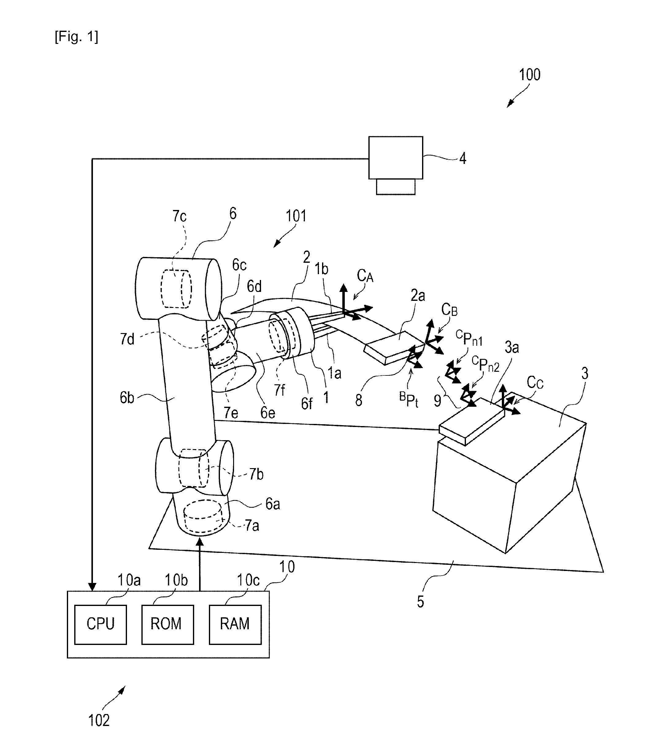
[0032]FIG. 1 is a diagram schematically illustrating a configuration of a robot according to a first embodiment of the present invention. A robot 100 includes a robot body 101 and a robot control apparatus 102 which controls the robot body 101.

[0033]The robot body 101 includes multijoint arm unit 6 including a plurality of link members 6a to 6f and a hand unit 1 disposed at an end of the arm unit 6. The arm unit 6 includes the link members 6a to 6f coupled with each other in series and may swing or rotate at joint portions.

[0034]Among the link members 6a to 6f, the link member 6a disposed in a proximal end (one end) of the arm unit 6 is fixed to a fixing surface (upper surface) of a base 5. Furthermore, the hand unit 1 is attached to the link member 6f disposed in a distal end (the other end) of the arm unit 6 among the link members 6a to 6f. The hand unit 1 of this embodiment includes a pair of fingers 1a and 1b and can grasp an object or release the object by opening and closing t...

second embodiment

[0070]Next, a robot according to a second embodiment of the present invention will be described. FIG. 6 is a diagram illustrating a trajectory of a first workpiece obtained by the robot according to the second embodiment of the present invention. Note that a configuration of the robot according to the second embodiment is the same as that of the first embodiment, and therefore, the same reference numerals are used for the description. However, operation of a robot body 101, that is, programs stored in a ROM 10b, is different from that of the first embodiment.

[0071]In the first embodiment, a case where the single target point 8 and the plurality of instruction points 9 are set has been described. Furthermore, the operation instructions, that is, the trajectory of the robot body 101, is set such that the target point 8 passes the instruction points 9. In the second embodiment, a plurality of target points 8 and a single instruction point 9 are set. Also in this case, a CPU 10a execute...

third embodiment

[0074]Next, a robot according to a third embodiment of the present invention will be described. FIG. 7 is a diagram schematically illustrating a configuration of a robot 100B according to a third embodiment of the present invention. Although the case where the camera 4 is fixed to the camera-mounting stage, not shown, has been described in the first embodiment, a camera 4 is fixed to a hand unit 1 in the third embodiment. Even when the camera 4 is thus fixed to the hand unit 1, coordinate data of a target point 8 and instruction points 9 in a coordinate system of the hand unit 1 is calculated by coordinate transformation using coordinate transformation matrices ATB and ATC irrespective of a position and orientation of the camera 4, and operation instructions are generated in accordance with results of the calculation. Specifically, the operation instructions are generated in accordance with the coordinate data of the target point 8 and the instruction points 9 obtained by the coordi...


PUM


Abstract

A first coordinate system CA of the hand unit, a second coordinate system CB of the first workpiece, and a third coordinate system CC of a second workpiece in a camera coordinate system are calculated (S2, S3, and S4). First and second coordinate transformation matrices ATB and ATC are calculated (S5 and S6). Coordinate data of a target point is set in the coordinate system of the first workpiece (S7). Coordinate data of an instruction point is set in the coordinate system of the second workpiece (S8). The coordinate data of the target point is subjected to coordinate transformation using the first coordinate transformation matrix ATB (S9). The coordinate data of the instruction point is subjected to coordinate transformation using the second coordinate transformation matrix ATC (S10). Operation instructions are generated using the converted coordinate data (S11).

Description

TECHNICAL FIELD[0001]The present invention relates to a robot control apparatus capable of attaching an object grasped by a robot to another object, a robot control method, a program, and a recording medium.BACKGROUND ART[0002]A robot which includes a robot body having a multijoint arm unit including a plurality of link members and a hand unit disposed in an end of the arm unit and which grasps an object serving as a first workpiece using the hand unit and attaches the grasped object to another object serving as a second workpiece has been generally used.[0003]Furthermore, various techniques of measuring a position using a camera including a stereo method have been used, and a 3D position of a feature point of an object included in an image captured by a camera can be measured by such a technique. Furthermore, a position and orientation of an object can be measured by measuring a plurality of feature points of an object. Moreover, various techniques of measuring a position using a p...

Claims


Application Information

Patent Timeline
Patent Type & Authority Applications(United States)
IPC IPC(8): B25J9/16
CPCB25J9/1607B25J9/1697B25J9/1679G05B2219/39022G05B2219/39063G05B2219/40082G05B2219/40609H01R43/26
Inventor NEGISHI, MAHITOSUZUKI, HIDEAKIIIZUKA, SHINSUKE
Owner CANON KK
Why Eureka
Try Eureka