Multi-Band/Multi-Mode Power Amplifier with Signal Path Hardware Sharing

a multi-mode power amplifier and signal path technology, applied in the direction of amplifier combinations, amplifier modifications to reduce noise influence, low noise amplifiers, etc., can solve the problems of increased die area and complexity, large die area, and duplication of circuits

Active Publication Date: 2014-01-16
QORVO INT PTE LTD
View PDF11 Cites 55 Cited by
  • Summary
  • Abstract
  • Description
  • Claims
  • Application Information

AI Technical Summary

Problems solved by technology

Having two separate signal paths results in a duplication of the bypass capacitors and thus requiring a much larger die area.
Having separate signal paths results in duplication of circuits, such as, the bias circuits of each of the signal paths.
It

Method used


Image

  • Multi-Band/Multi-Mode Power Amplifier with Signal Path Hardware Sharing
  • Multi-Band/Multi-Mode Power Amplifier with Signal Path Hardware Sharing
  • Multi-Band/Multi-Mode Power Amplifier with Signal Path Hardware Sharing

Examples


Embodiment Construction

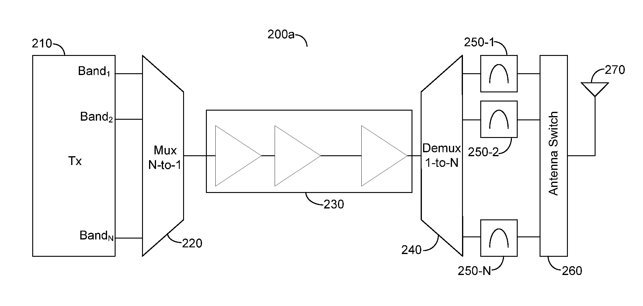
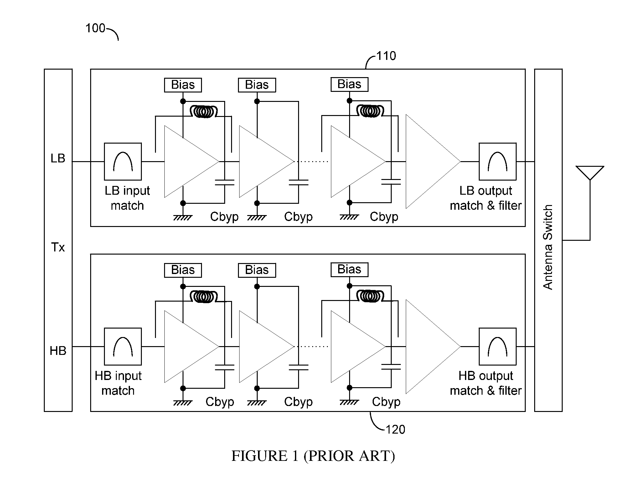
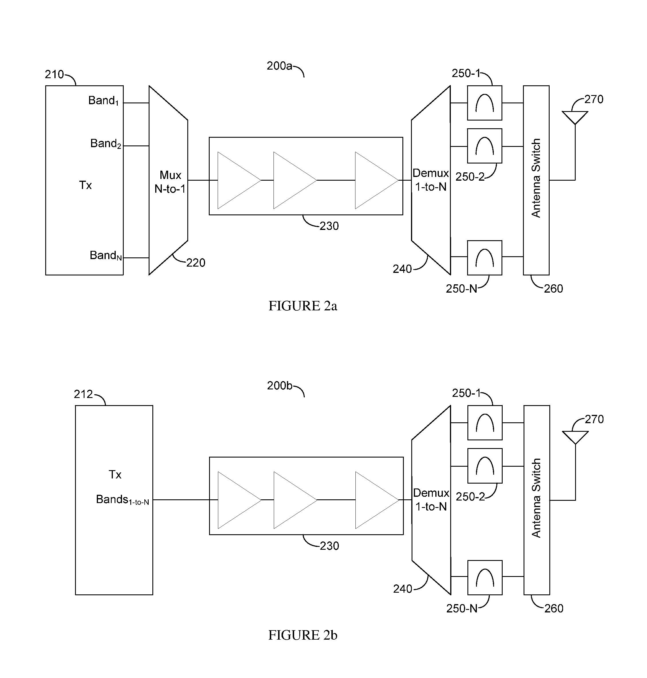
[0021]Existing multi-band / multi-mode (MB / MM) power amplifiers (PAs) use separate signal paths for the different covered frequency bands. This results in a large degree of hardware duplication and to a large die size and cost. Solutions that achieve hardware sharing between the different signal paths of a MB / MM PAs are shown. Such sharing includes bias circuit and bypass capacitors sharing, as well as sharing front-end stages and the output stage of the PA. Signal multiplexing may be realized in the transmitter or at the PA front-end while the signal de-multiplexing can be realized either in the PA output stage or at the front-end of the output stage. Such circuits can be applied with saturated and linear MB / MM PAs with adjacent or non-adjacent bands.

[0022]A multi-band PA system may use multiple bands belonging to the same standard, or bands belonging to several different communication standards, also called modes. In this document such PAs shall be referred to as MB / MM PAs. However,...


PUM


Abstract

Existing multi-band/multi-mode (MB/MM) power amplifiers (PAs) use separate signal paths for the different covered frequency bands. This results in a large degree of hardware duplication and to a large die size and cost. Solutions that achieve hardware sharing between the different signal paths of MB/MM PAs are shown. Such sharing includes bias circuit and bypass capacitors sharing, as well as sharing front-end stages and the output stage of the PA. Signal multiplexing may be realized in the transmitter or at the PA front-end while the signal de-multiplexing can be realized either in the PA output stage or at the front-end of the output stage. Such circuits can be applied with saturated and linear MB/MM PAs with adjacent or non-adjacent bands.

Description

BACKGROUND OF THE INVENTION[0001]1. Field of the Invention[0002]The invention generally relates to multi-band / multi-mode power amplifiers and more particularly to multi-band / multi-mode power amplifiers that share hardware of the signal path.[0003]2. Prior Art[0004]Prior art multi-band / multi-mode (MB / MM) power amplifiers (PAs) use separate signal paths for each supported band. FIG. 1 shows such an exemplary prior art multi-band PA 100 having a low-band (LB) signal path 110 and a high-band (HB) signal path 120. It is usually the case that the bypass capacitors of the radio frequency (RF) signal path stages dominate the die area on which the PA is implemented. Having two separate signal paths results in a duplication of the bypass capacitors and thus requiring a much larger die area. If more than two signal paths are used then the hit grows proportionately.[0005]Having separate signal paths results in duplication of circuits, such as, the bias circuits of each of the signal paths. Furt...

Claims


Application Information

Patent Timeline
IPC IPC(8): H03F3/20H03F3/68
CPCH03F1/56H03F3/195H03F3/245H03F2200/111H03F2200/222H03F2200/294H03F2200/387H03F2200/405H03F2200/429H03F2203/7209H03F2203/7215H03F2203/7221H03F2203/7236H03F3/68H03F1/07H03F1/0288H03F1/301H03F3/602H03F1/26H03F3/211H03F2203/21131H03F2203/21139
Inventor SCOTT, BAKERMAXIM, GEORGE
Owner QORVO INT PTE LTD
Why Eureka
Try Eureka