In-Vehicle Camera Unit Having Camera Built Into Body
- Summary
- Abstract
- Description
- Claims
- Application Information
AI Technical Summary
Benefits of technology
Problems solved by technology
Method used
Image

Examples
first embodiment
[0022]1. The configuration of the in-vehicle camera unit
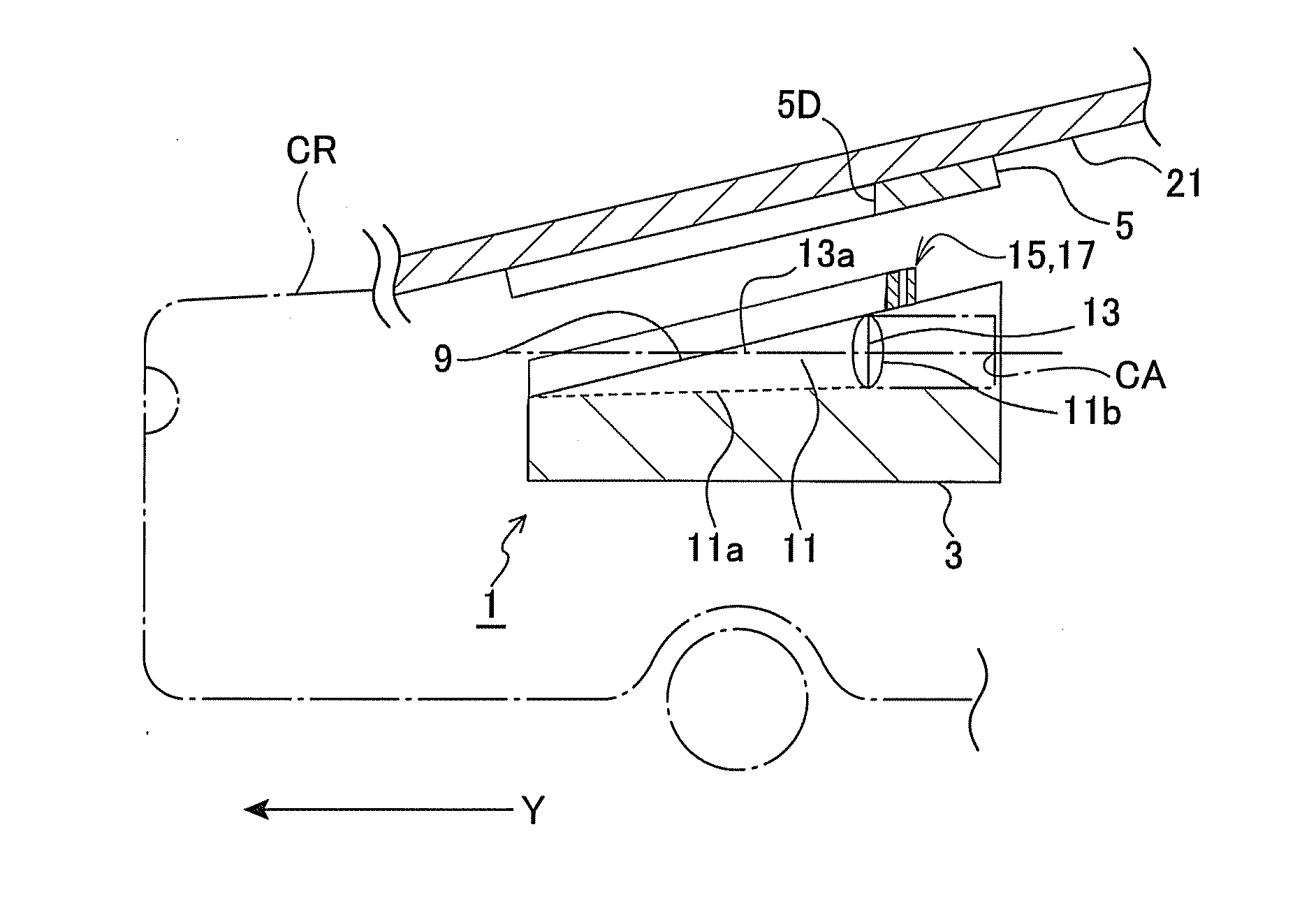
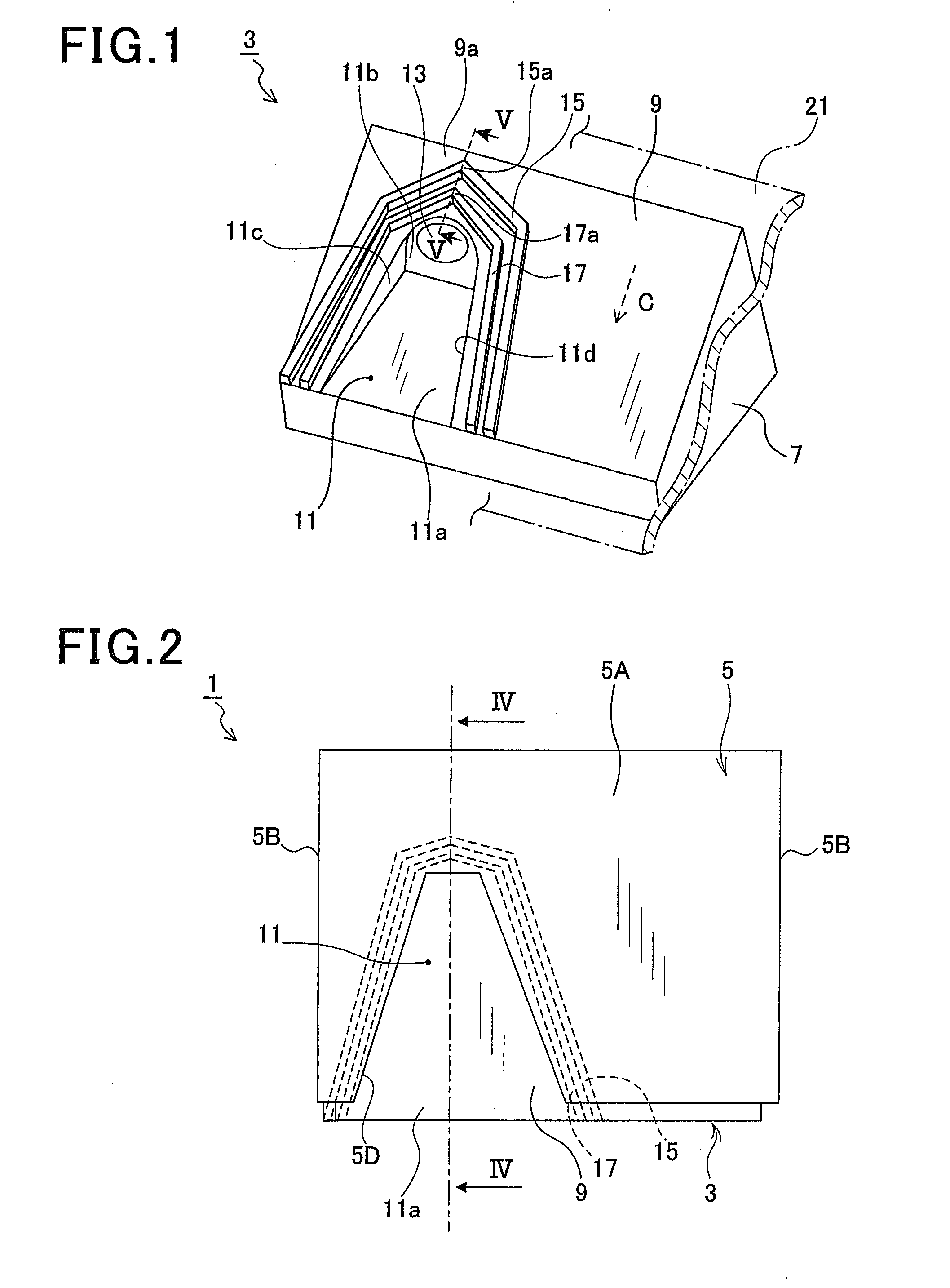
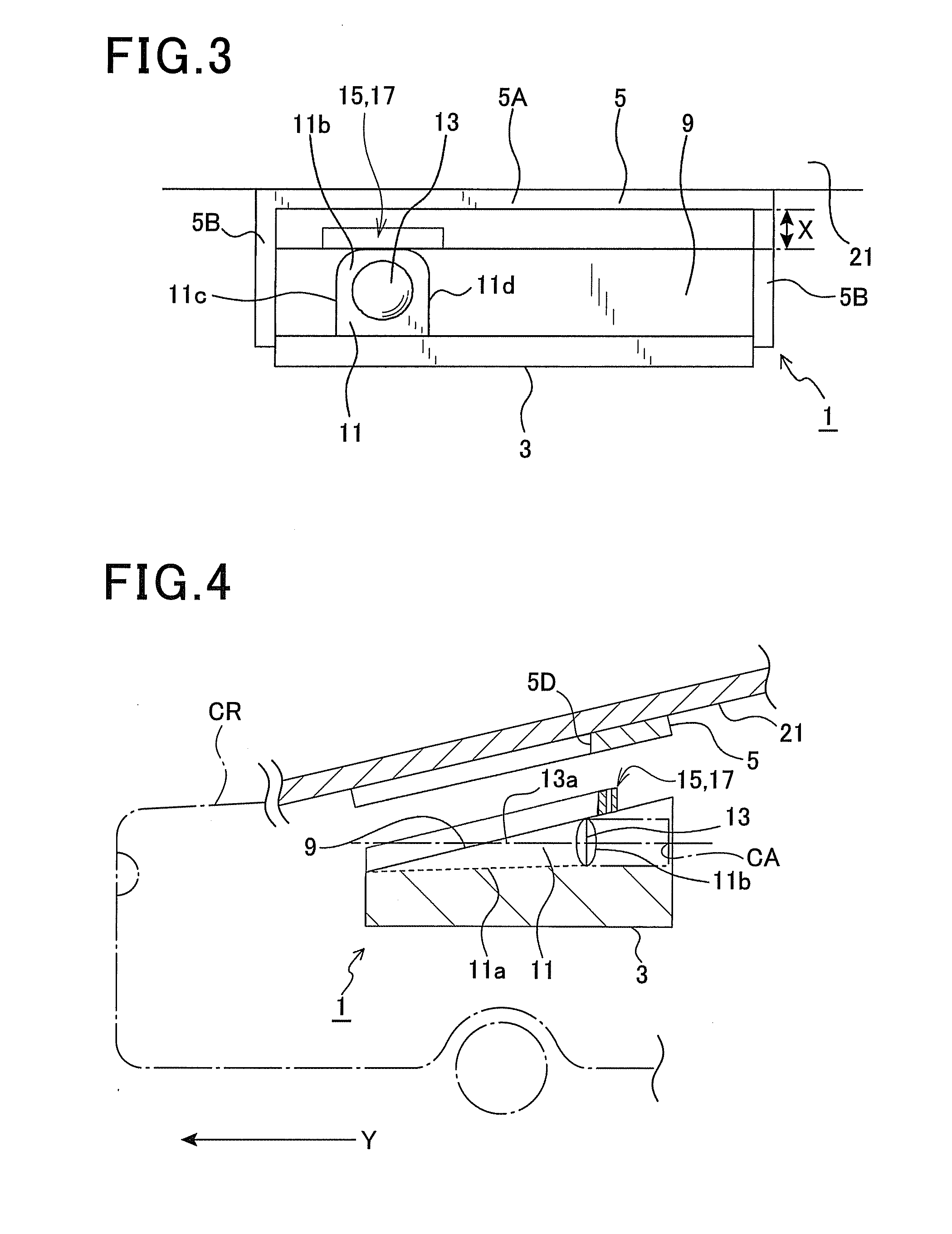
[0023]A first embodiment will be described with reference to FIG. 1 to FIG. 5A. FIG. 1 is a perspective view of a main portion 3 of an in-vehicle camera unit 1. The main portion 3 is described below. FIG. 2 is a top view of the in-vehicle camera unit 1. FIG. 3 is a front view of the in-vehicle camera unit 1. FIG. 4 is a cross sectional side view taken from line IV-IV of FIG. 2. FIG. 5A is a cross-section view taken from line V-V which shows prevention members 15, 17 and the periphery of them. The prevention members 15, 17 are described below.
[0024]The in-vehicle camera unit 1 has a main portion 3 and bracket 5. As shown in FIG. 1, the main portion 3 has a body 7 and compositions (not shown in figures) of camera CA which are publicly known. The compositions including lens 13 are accommodated in the body 7. The in-vehicle camera unit 1 of this embodiment is attached to a car, with the lens 13 facing the windshield 21 of the car. ...
second embodiment
[0047]Hereinafter, the configuration of the in-vehicle camera 1 will be described with reference to FIGS. 7 to 12. FIG. 7 is a perspective view of the in-vehicle camera 1. FIG. 8 is a perspective view of the in-vehicle camera 1 (from which a hood 8 described later has been removed). FIG. 9 is a sectional side view taken along a line A-A in FIG. 7. FIG. 10 is a perspective view of a bracket 47 described later. FIG. 11 is a diagram for explaining a method of attaching the in-vehicle camera 1 to the bracket 47. FIG. 12 is a diagram for explaining a state in which the in-vehicle camera 1 is attached to the bracket 47.
[0048]The in-vehicle camera 1 is attached in a vehicle interior. As shown in FIGS. 7 and 8, the in-vehicle camera 1 includes a body 7, a prevention member 16 and components (not shown) of a well-known camera housed in the body 7. All of the top surface 9 of the body 7 is inclined downward toward the front side (in the direction B shown in FIG. 7, i.e. a direction which a le...
PUM
 Abstract
Description
Claims
Application Information
 - Generate Ideas
- Intellectual Property
- Life Sciences
- Materials
- Tech Scout
- Unparalleled Data Quality
- Higher Quality Content
- 60% Fewer Hallucinations
Browse by: Latest US Patents, China's latest patents, Technical Efficacy Thesaurus, Application Domain, Technology Topic, Popular Technical Reports.
© 2025 PatSnap. All rights reserved.Legal|Privacy policy|Modern Slavery Act Transparency Statement|Sitemap|About US| Contact US: help@patsnap.com