
Systems and Methods for Detecting and Controlling Transmission Devices

a transmission device and system technology, applied in transmission monitoring, high-level techniques, power management, etc., can solve problems such as cellular phone use or wireless transmission devices on premises or even possession of cellular phones

Active Publication Date: 2014-01-16
BINJ LAB
View PDF3 Cites 98 Cited by
  • Summary
  • Abstract
  • Description
  • Claims
  • Application Information

AI Technical Summary

Benefits of technology

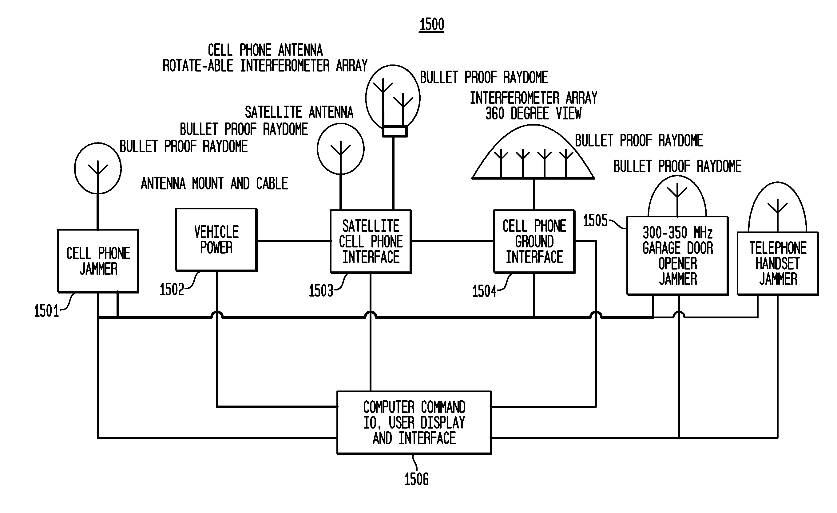
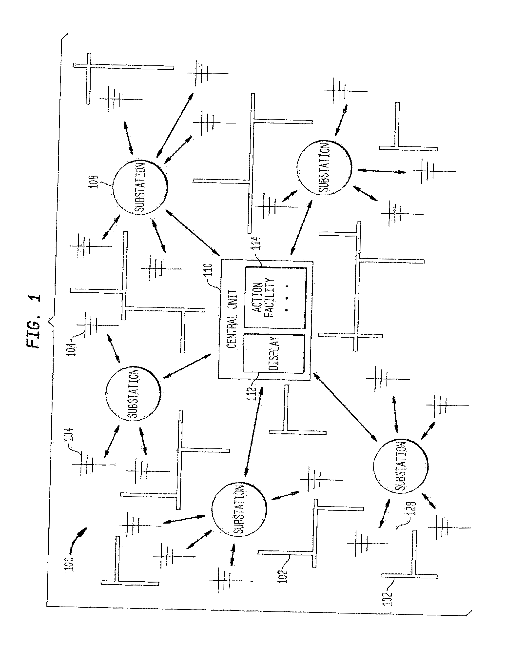
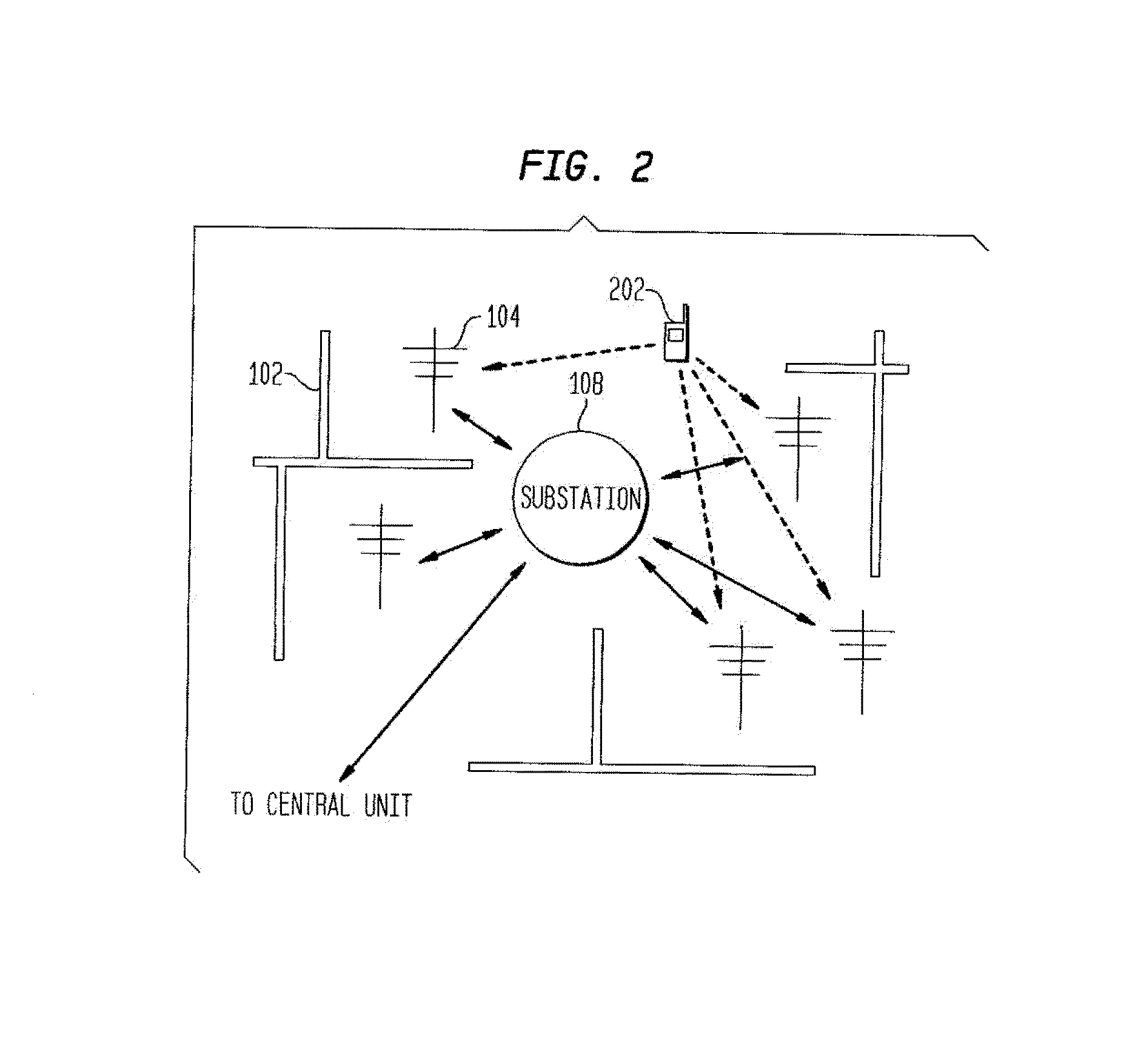
The patent provides methods and systems for detecting and locating wireless communication devices, such as cell phones, in an obstruction-rich environment like a correctional facility or a mall. The methods can detect the transmission of signals from the devices and determine their location using triangulation or extrapolation techniques. This information can then be communicated to an action facility for taking appropriate actions. The technical effects of the patent include the ability to locate and manage wireless communication facilities, as well as detect and track individuals who use wireless devices to communicate.

Problems solved by technology

There are many facilities, such as government buildings, and in particular correctional facilities, such as prisons, that do not permit cellular phone usage or wireless transmission devices on the premises or even possession of cellular phones being used by criminals.

Method used


Image

  • Systems and Methods for Detecting and Controlling Transmission Devices
  • Systems and Methods for Detecting and Controlling Transmission Devices
  • Systems and Methods for Detecting and Controlling Transmission Devices

Examples


embodiment 1600

[0108]FIG. 16 Illustrates a block diagram of an embodiment of a Cell Phone and Wireless Transmission Detection Facility in accordance with the principles of the invention. In the illustrated embodiment 1600, antenna 1602 is a multi-band directional array that operates to detect signals in a low band and in a high band (835 and 1.85 GHz range, respectively), a two way radio band (465 MHz), a Wi-Fi, a Bluetooth band (2.5 GHz) and PAL (Personal Alarm Locator) band (950 MHz). In the illustrated embodiment, the antenna connects to two components, first to a detector (1603) and also to a decoder (1604). The detector 1603 and decoder 1604 decodes the PAL Identification signal and may further decode biometric information, emergency information. In other embodiments, detector 1603 and decoder 1604 are configured to decode cell phone identifications. Antenna 1602 provides detected signals to a 6 way input switch (1605). The output of switch 1605 is connected to a wideband RF amplifier (1606)....

embodiment 1800

[0164]FIG. 18 illustrates a system 1800 for implementing the principles of the invention shown herein. In this exemplary system embodiment 1800, input data is received from sources 1801 over network 1850 and is processed in accordance with one or more programs, either software or firmware, executed by processing system 1810. The results of processing system 1810 may then be transmitted over network 1880 for viewing on display 1892, reporting device 1890 and / or a second processing system 1895.

[0165]Processing system 1810 includes one or more input / output devices 1802 that receive data from the illustrated sources or devices 1801 over network 1850. The received data is then applied to processor 1803, which is in communication with input / output device 1802 and memory 1804. Input / output devices 1802, processor 1803 and memory 1804 may communicate over a communication medium 1825. Communication medium 1825 may represent a communication network, e.g., ISA, PCI, PCMCIA bus, one or more int...

first embodiment

[0205]FIG. 28 illustrates one embodiment of the invention, where a restricted cell phone (2801) is being controlled by a communication control unit (2802) when a wireless communications device (2801) is detected within a restricted area (2800), and this phone tries to make a 911 call, there is several ways to make this possible and to insure security and restriction on the use of that cell phone. the invention is to backhaul (2806) the call to a 911 to emergency response staff (2807) specifically designed to handle this restricted coverage area (2800). This methodology will provide for quicker response and the personnel (2807) handling the call center will be specially trained to respond to the emergency and this will eliminate wasting personnel outside the restricted area to respond to someone trying to defeat the “no cell phone security system.” Additionally, the law enforcement personnel within the jurisdiction of the secure facility responding to the 911 call may monitor the sit...


PUM


Abstract

A method of detecting, controlling and managing transmission of a transmitting device within a facility is disclosed. The method involves transmitting information to the transmission device, detecting a response transmission from the transmission device by a least one transmission detection facility, extracting identification information associated with the transmission device in response to the transmitted information; and determining a location of the transmission device based on the response transmission received by the at least one received transmission detection facility, wherein the response transmissions are sorted by the identification information, determining an allowability of the located transmission device within the set area and reducing a power level of a transmitted signal for a predetermined period of time, when allowability is indicated.

Description

CLAIM OF PRIORITY[0001]This application claims the benefit of the earlier filing date, pursuant to 35 USC §119, to that patent application entitled “Systems and Methods for Detecting and Controlling Transmission Devices” filed in the United States Patent and Trademark Office on Jul. 6, 2012 and afforded Ser. No. 61 / 668,852, and, pursuant to §120, as a continuation-in-part[0002]to that patent application entitled “System and Method of Detection of Transmission Facilities,” filed in the United States Patent and Trademark Office on Aug. 28, 2010 and afforded Ser. No. 12 / 870,808 (BINJ-0100CIP-5),[0003]which claimed the benefit of the earlier filing date, pursuant to 35 USC 119, to U.S. Provisional App. No. 61 / 237,682, entitled “Method and System for Determining a Location and Tracking of a Wireless Device,” filed on Aug. 28, 2009 (BINJ-P-0106) and to U.S. Provisional App. No. 61 / 264,838, entitled “System and Method of Detection and Allowing Access of Transmission Facilities, filed on No...

Claims


Application Information

Patent Timeline
Patent Type & Authority Applications(United States)
IPC IPC(8): H04W64/00H04M1/72457
CPCH04W64/00H04W64/006H04W8/005H04W12/12H04W24/10H04W48/16H04W48/04H04W4/021Y02D30/70H04W12/64H04B17/318H04W52/283H04M1/72457H04W12/08H04W16/32
Inventor NOONAN, JOSESPH S.
Owner BINJ LAB
Learn More