Pivotal pulley for exercise machine

Inactive Publication Date: 2014-01-16
CHEN PAUL
View PDF7 Cites 9 Cited by
  • Summary
  • Abstract
  • Description
  • Claims
  • Application Information

AI Technical Summary

Benefits of technology

[0013]The primary objective of the present invention is to provide a physical exercising machine including a pivotal pulley device for suitably and stably supporting or engaging with a pulling wire or cable or the like and for preventing the pulling w

Problems solved by technology

However, the pulling wires or cables are required to be engaged with one or more pulleys, and the pulleys are normally solidly and stably attached or mounted or secured on the supporting stand or the exercising stations or members or facilities and the like, and the pulleys may not be pivoted or rotated relative to the supporting stand or the exercising stations or members or facilities and the like such that the pulling wires or cables may have a good chance to be disengaged or removed from the pulleys inadvertently while in use.
However, the threaded bolt or screw and the foot support may be inclined or tilted a lot relative to the su

Method used


Image

  • Pivotal pulley for exercise machine
  • Pivotal pulley for exercise machine
  • Pivotal pulley for exercise machine

Examples


Embodiment Construction

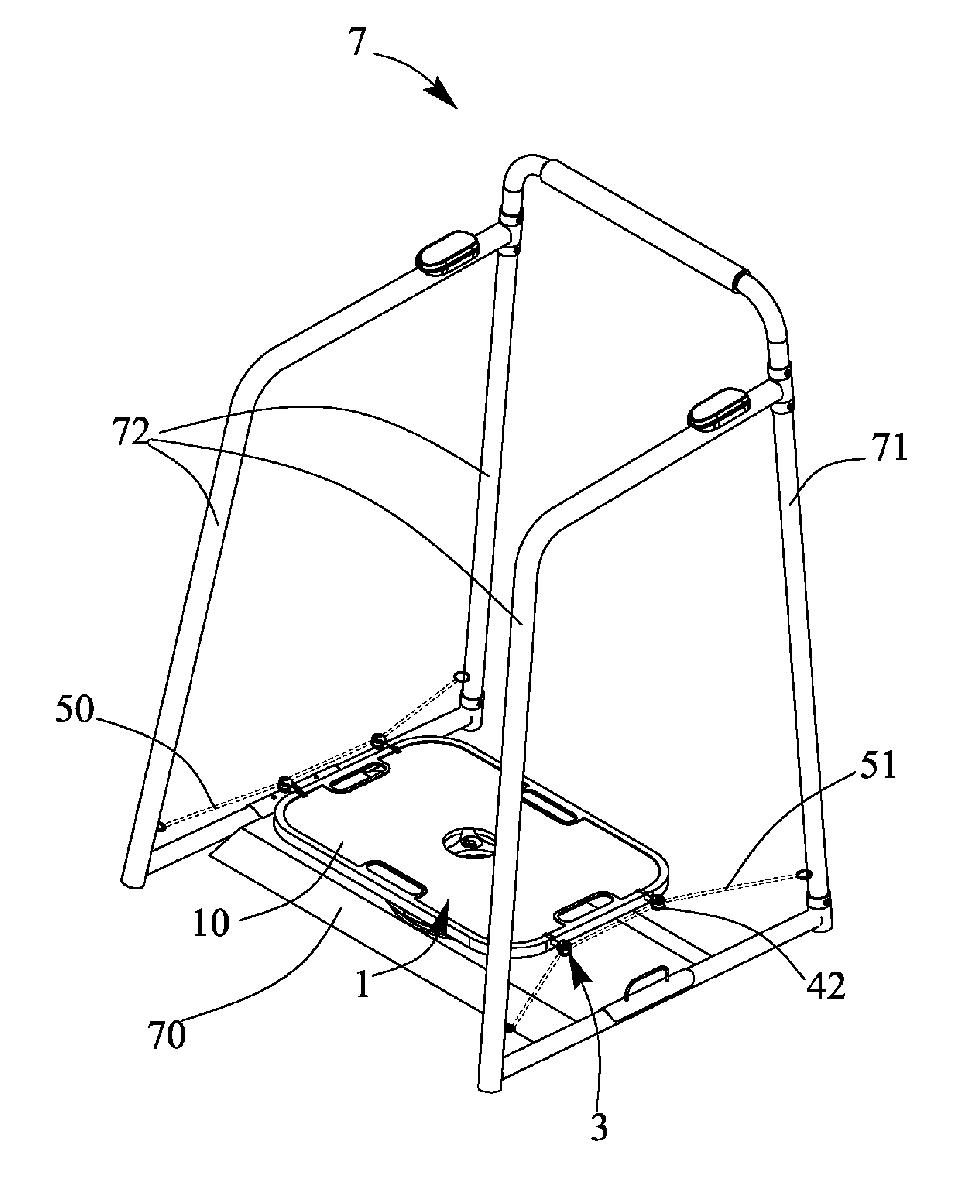
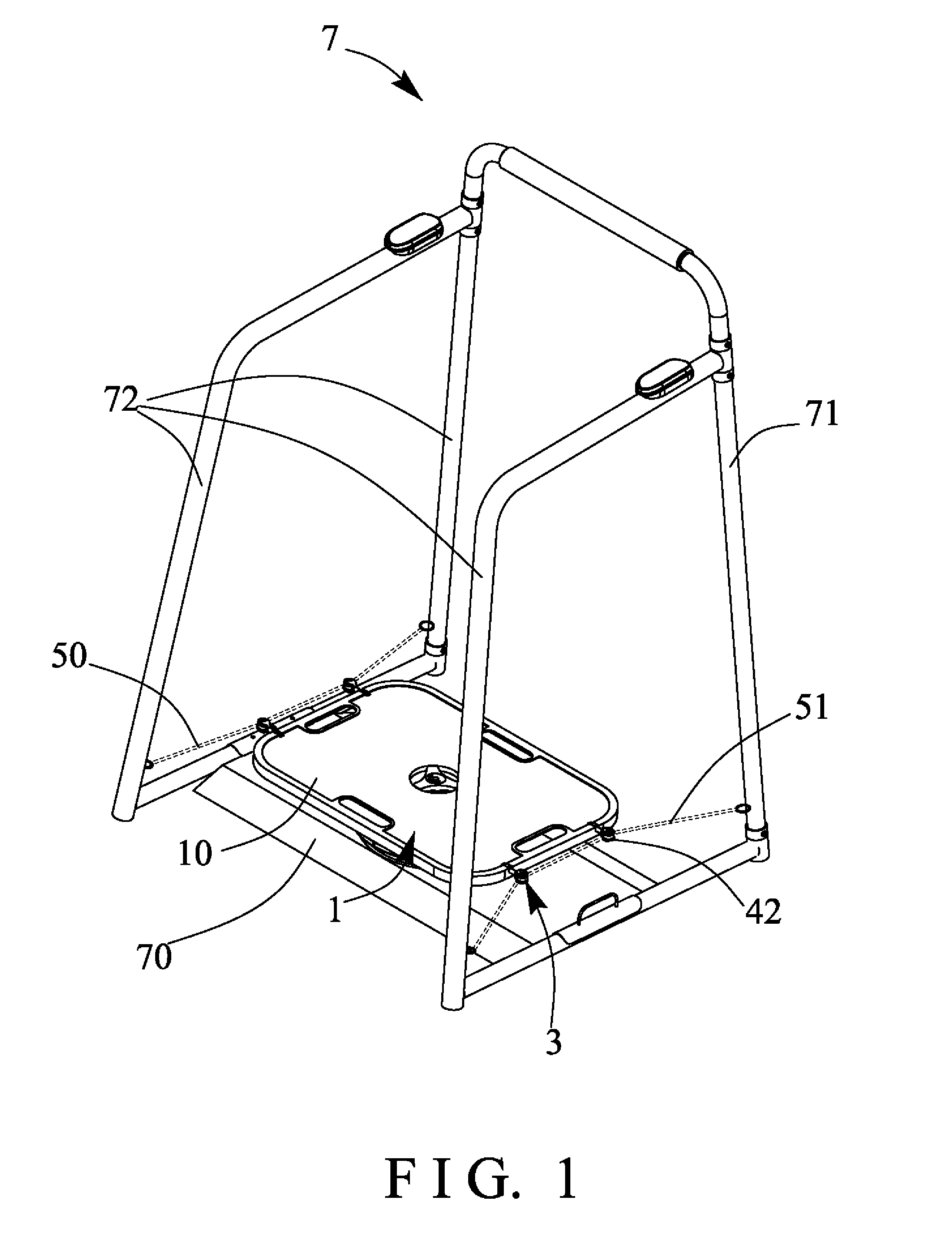
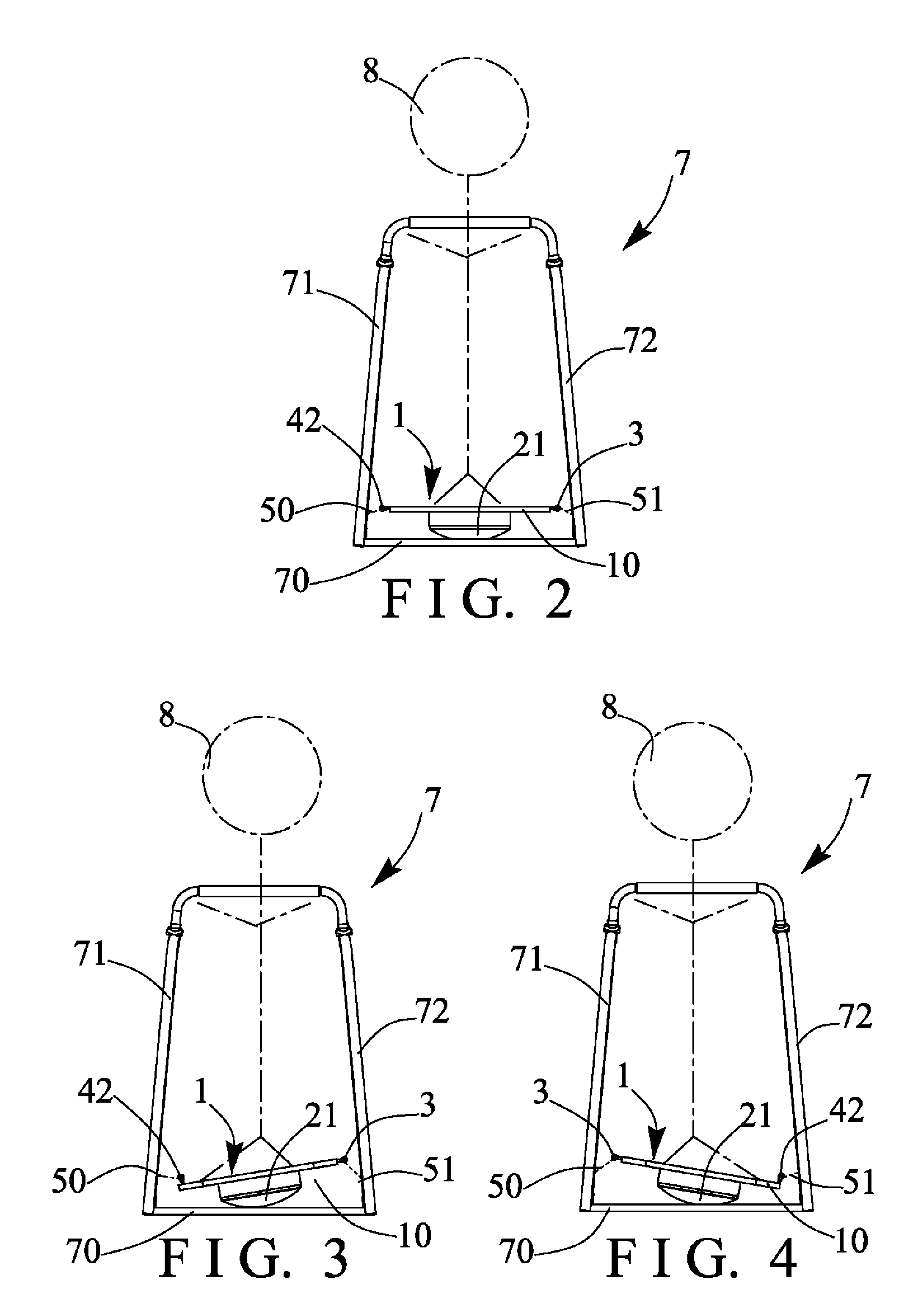
[0037]Referring to the drawings, and initially to FIGS. 1-4, a physical exercising machine in accordance with the present invention comprises a tilting or balancing exerciser 1 including a stationery frame or base member 10 (FIGS. 5-7) including a chamber 11 formed therein (FIGS. 7, 11-13), such as formed in the bottom portion thereof and formed or defined by an upper platform 12 and an outer peripheral wall or fence 13, and including one or more (such as four) apertures 14 formed in or formed through the platform 12 and communicative with the chamber 11 of the base member 10 for attaching or mounting or securing or engaging with pivotal pulley devices 3 respectively, and including one or more (such as four) lock notches 15 formed therein (FIGS. 7 and 11-13) and disposed or located below the respective apertures 14 and communicative with the apertures 14 of the base member 10 respectively (FIGS. 11-13) for anchoring or securing or retaining the pivotal pulley devices 3 to the base m...


PUM


Abstract

A physical exercising machine includes a platform to support a user, an aperture formed in the platform, a pulley device includes a shaft for engaging with the aperture of the base and for pivotally attaching to the base, a shank is extended from the shaft and pivotal relative to the base with the shaft, a bracket is rotatably attached to the shank, and a pulley member is rotatably attached to the bracket with a spindle, and a cable is engaged with the pulley member, the pulley member is pivotal relative to the base with the shaft and rotatable relative to the shank for preventing the pulling cable from being disengaged from the pulley member and for allowing the user to suitably actuate or operate the pulling cable.

Description

BACKGROUND OF THE INVENTION[0001]1. Field of the Invention[0002]The present invention relates to a physical exercising machine, and more particularly to a pull type physical exercising machine including a pivotal pulley device for suitably and stably supporting or engaging with a pulling wire or cable or the like and for preventing the pulling wire or cable from being disengaged from the pivotal pulley device and for allowing the user to suitably and effectively actuate or operate the pulling wire or cable in order to suitably and stably exercise or train the upper muscle groups of the user.[0003]2. Description of the Prior Art[0004]Typical physical exercising machines comprise a supporting stand disposed or supported on the supporting ground or surface for supporting the user thereon, one or more pulleys attached or mounted or secured on the supporting stand for engaging with a pulling wire or cable or the like, and a handle or hand grip coupled to the pulling wire or cable for pul...

Claims


Application Information

Patent Timeline
IPC IPC(8): A63B26/00
CPCA63B22/18A63B26/003A63B2208/12A63B21/152A63B21/154A63B21/156A63B22/16A63B2071/0072A63B69/0057
Inventor CHEN, PAUL
Owner CHEN PAUL
Why Eureka
Try Eureka