Visual indicator status recognition

a technology of status recognition and indicators, applied in the field of visual indicator status recognition, can solve problems such as the type of objects that are susceptible to damag

Active Publication Date: 2014-01-23
SHOCKWATCH
View PDF11 Cites 22 Cited by
  • Summary
  • Abstract
  • Description
  • Claims
  • Application Information

AI Technical Summary

Problems solved by technology

For example, some types of objects may be susceptibl...

Method used


Image

  • Visual indicator status recognition
  • Visual indicator status recognition
  • Visual indicator status recognition

Examples


Embodiment Construction

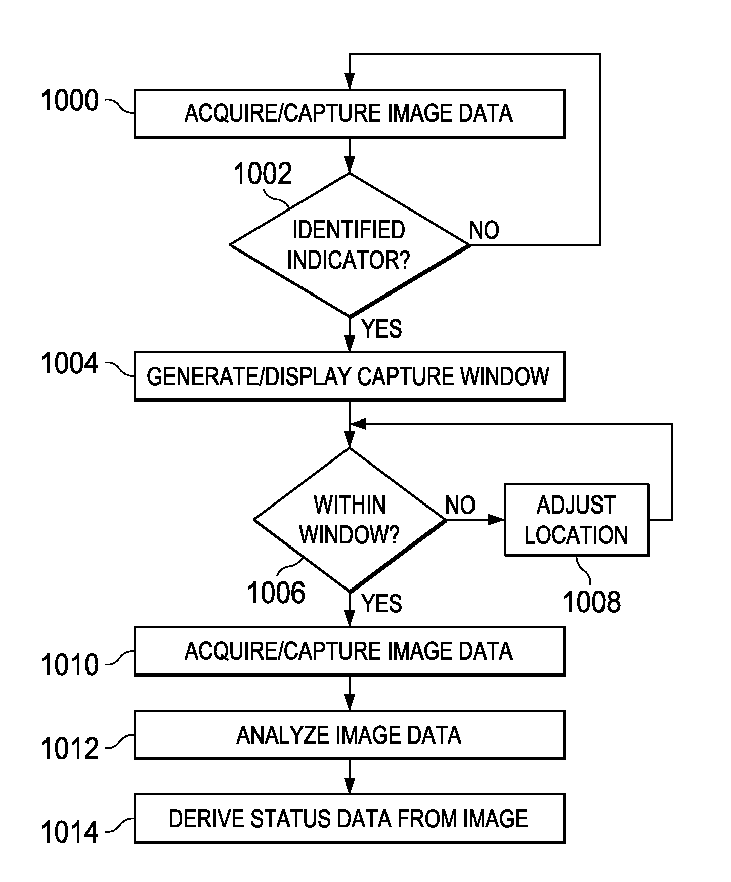
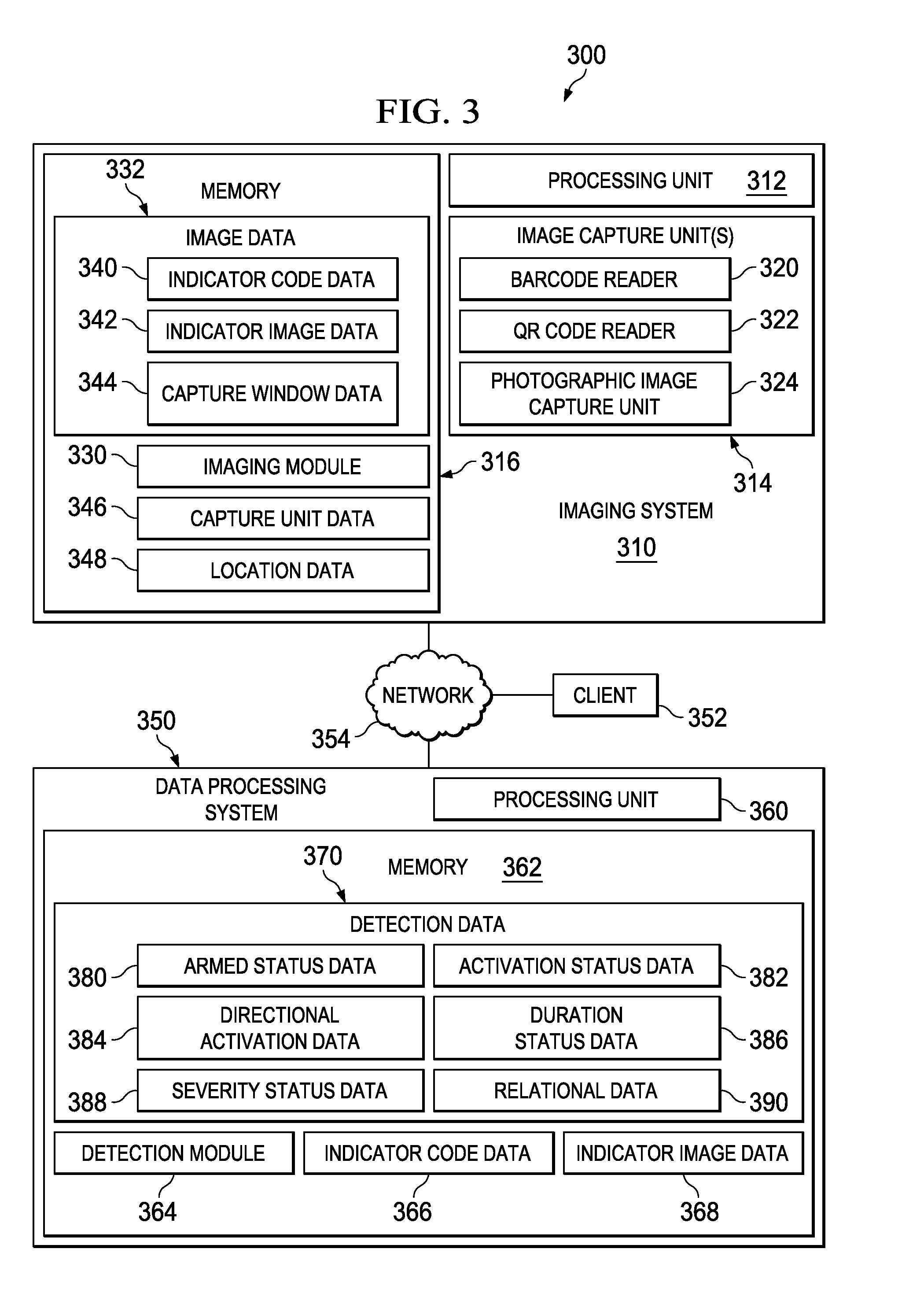
[0016]Embodiments of the present disclosure provide a method, system and computer program product for visual indicator status recognition. For example, in some embodiments, the method and technique includes an imaging system configured to capture a first optical data of an indicator, the imaging system configured to verify indicator code indicia is derivable from the first optical data. Responsive to verifying that the indicator code indicia is derivable from the first optical data, the imaging system is configured to capture a second optical data of the indicator. The system and technique also includes a detection module executable by a processing unit to analyze the second optical data and derive status information of the indicator. Thus, embodiments of the present disclosure enable visual indicator status information to be captured / digitized to enable environmental conditions monitored by such indicator to be monitored / tracked and / or readily available to a customer or other entit...


PUM


Abstract

A system and technique for visual indicator status recognition includes an imaging system configured to capture a first optical data of an indicator, the imaging system configured to verify indicator code indicia is derivable from the first optical data. Responsive to verifying that the indicator code indicia is derivable from the first optical data, the imaging system is configured to capture a second optical data of the indicator. The system and technique also includes a detection module executable by a processing unit to analyze the second optical data and derive status information of the indicator.

Description

BACKGROUND[0001]During manufacturing, storage or transit, many types of objects need to be monitored due to the sensitivity or fragility of the objects. For example, some types of objects may be susceptible to damage if dropped or a significant impact is received. Other types of objects may need to be monitored for temperature conditions. Thus, for quality control purposes and / or the general monitoring of transportation conditions, it is desirable to determine and / or verify the environmental conditions to which the object has been exposed.BRIEF SUMMARY[0002]According to one aspect of the present disclosure, a system, method a computer program product for visual indicator status recognition is disclosed. The system and technique for visual indicator status recognition includes an imaging system configured to capture a first optical data of an indicator, the imaging system configured to verify indicator code indicia is derivable from the first optical data. Responsive to verifying tha...

Claims


Application Information

Patent Timeline
IPC IPC(8): G06K9/78
CPCG06K9/78G01N31/229G06K19/0717
Inventor BRANCH, CLINTON A.KERR, ANGELA K.KOHLERITER, KEVIN M.
Owner SHOCKWATCH
Why Eureka
Try Eureka