
Optical transmission system, receiving-end device, and optical transmission method

Active Publication Date: 2014-01-23
NEC CORP
View PDF13 Cites 7 Cited by
  • Summary
  • Abstract
  • Description
  • Claims
  • Application Information

AI Technical Summary

Benefits of technology

[0009]To solve the above problems, an exemplary object of the invention is to provide an optical transmission system, a receiving-end device, and an optical tra

Problems solved by technology

There is thus a problem that the cost increases to build the redundant configuration.
There is also a problem that complicated processing such as switching from the operating transponder to the redundant transponder and switching from the operating path to the redundant path is required.
However, in the both systems disclosed in those patent literatures, components such as a redundant transponder, an op

Method used


Image

  • Optical transmission system, receiving-end device, and optical transmission method
  • Optical transmission system, receiving-end device, and optical transmission method
  • Optical transmission system, receiving-end device, and optical transmission method

Examples


Example

[0019][Exemplary embodiment]

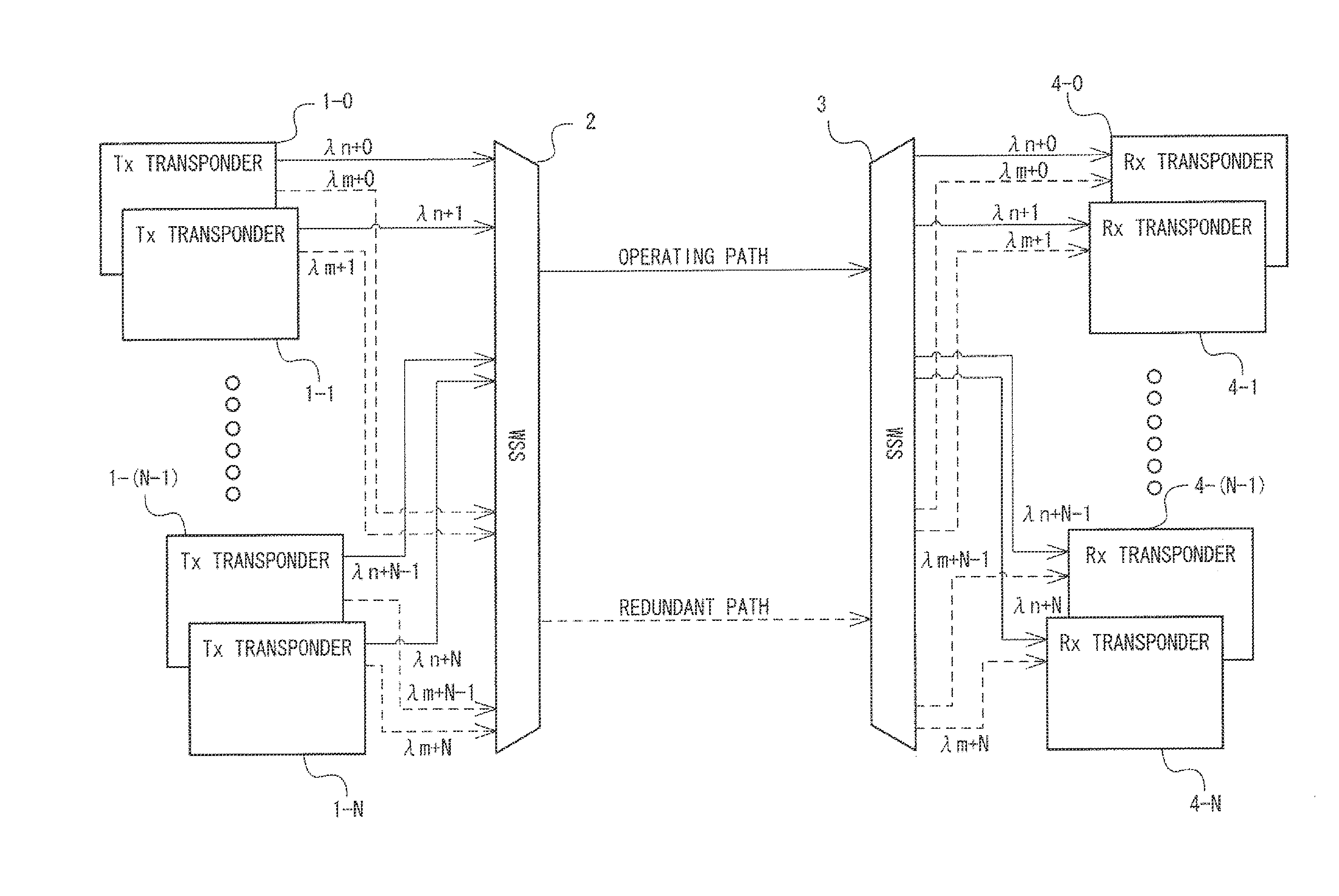
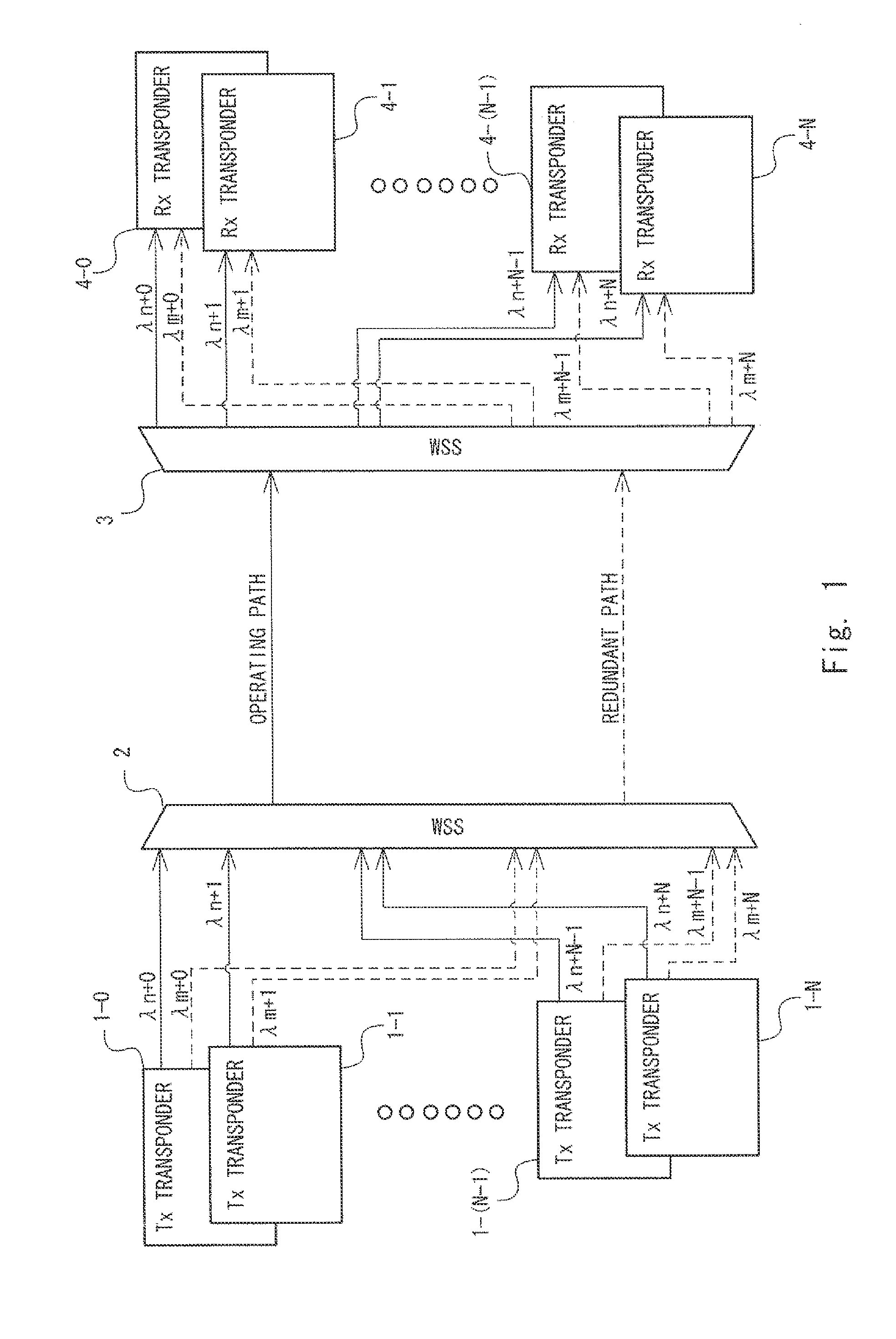
[0020]A configuration of a wavelength division multiplexing transmission system according to an exemplary embodiment of the invention is described hereinafter with reference to FIG. 1. FIG. 1 is a block diagram of a wavelength division multiplexing transmission system according to an exemplary embodiment of the invention.

[0021]The wavelength division multiplexing transmission system includes Tx transponders 1-0 to 1-N, wavelength selective switches (WSS) 2 and 3, and Rx transponders 4-0 to 4-N. N is any positive integer.

[0022]Note that the Tx transponders 1-0 to 1-N are hereinafter also referred to collectively as “Tx transponders 1”, and the Rx transponders 4-0 to 4-N are also referred to collectively as “Rx transponders 4”. Further, optical signals (wavelengths λn+0 to λn+N) that are respectively transmitted from the Tx transponders 1-0 to 1-N through an operating path are referred to collectively as “optical signals for operating path”, and optical sig...


PUM


Abstract

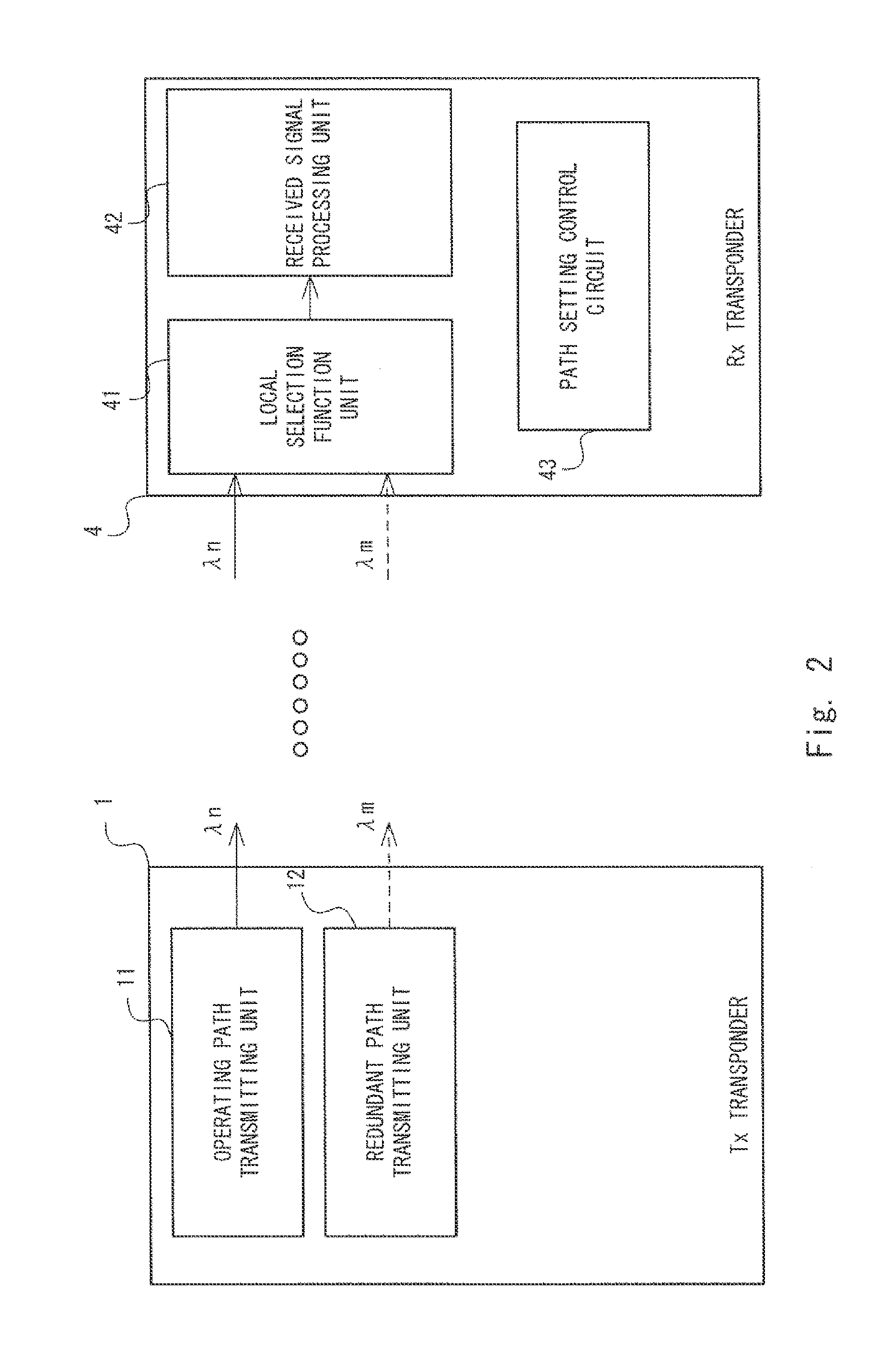
An optical transmission system includes an optical transmitting device (8) and an optical receiving device (9). The optical transmitting device (8) includes an operating channel transmitting unit (81) that transmits a first optical signal to an operating channel, and a redundant channel transmitting unit (82) that transmits a second optical signal having the same information as the first optical signal to a redundant channel. The optical receiving device (9) includes a local selection function unit (91) that has a function of selecting a wavelength of the first optical signal or the second optical signal transmitted from the optical transmitting device (8), a channel setting control unit (92) that sets a wavelength to be selected by the local selection function unit (91), and a receiving unit (93) that receives the first optical signal or the second optical signal having the wavelength selected by the local selection function unit (91).

Description

INCORPORATION BY REFERENCE[0001]This application is based upon and claims the benefit of priority from Japanese patent application No. 2012-162560, filed on Jul. 23, 2012, the disclosure of which is incorporated herein in its entirety by reference.BACKGROUND OF THE INVENTION[0002]1. Technical Field[0003]The present invention relates to an optical transmission system, a receiving-end device, and an optical transmission method and, particularly, to a technique to transmit and receive optical signals having the same information through each of an operational channel and a redundant channel.[0004]2. Background Art[0005]One example of a redundant configuration of the wavelength division multiplexing (WDM) transmission system is a 1:1 configuration where the redundant configuration is composed of an operating transponder for mainly making the wavelength division multiplexing transmission system operate and a redundant transponder for making redundancy separately as a spare. Another exampl...

Claims


Application Information

Patent Timeline
IPC IPC(8): H04J14/02
CPCH04J14/0293H04J14/0294H04J14/0295
Inventor NANJO, TATSUNORI
Owner NEC CORP
Learn More